
COMPUSHIFT Sport and COMPUSHIFT Pro Install Guide
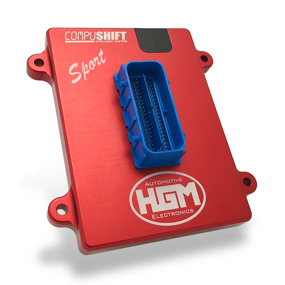
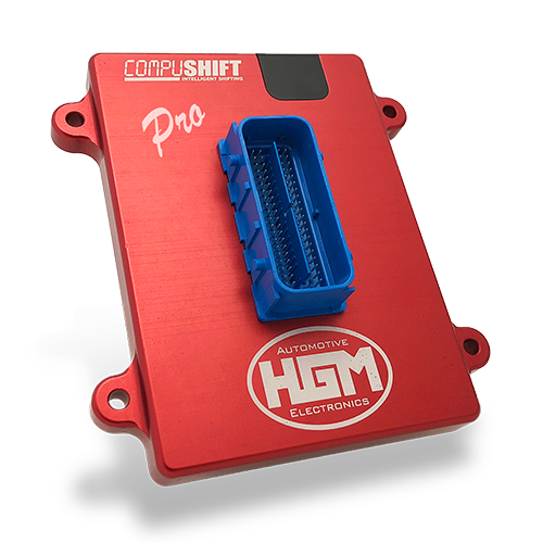

Congratulations on your purchase of a COMPUSHIFT
HGM Automotive Electronics’ next-generation precision shift controller. The sturdy COMPUSHIFT housing is water resistant to 3’ / 1m. Though we prefer you mount inside the vehicle, the controller can be mounted in the engine compartment or even under the vehicle, provided it is away from heat sources. Plug-and-play connections and versatile factory tuning make installation a breeze.
This guide takes you through the basic steps for installing your transmission controller.
For more details, including How-To videos, specifications, pinout information and more, go online: http://manuals.hgmelectronics.com.
We’re Here to Help
If you purchased directly from HGM, your COMPUSHIFT is calibrated to your unique vehicle specs, but be sure to ask for help if you need it. Throughout installation, we’ll work with you over the phone to help you fine-tune to perfection. As you get to know your system, we’ll make sure you know how to make changes on your own, so you can manage your own adjustments like a pro.

HGM Automotive Electronics, Inc.
2751 Plaza Del Amo, Suite 305
Torrance, CA, 90503 U.S.A.
877-SHIFT-UP (877-744-3887)
310-787-9260
support@hgmelectronics.com
Before You Begin
Check the Invoice / Packing Slip
Your COMPUSHIFT transmission controller should have been configured for your specific application. Check the packing slip to confirm you’ve received the correct components for your vehicle.
Specifically, check the following:
Transmission Type
Engine type
Throttle position sensor type
Inspect Your Transmission
Before beginning the installation, make sure your transmission is in good condition.
A malfunctioning transmission may damage the unit and void your warranty.
If you’re in doubt, see a qualified transmission repair shop for a full inspection.
Be sure the transmission is properly filled with oil before starting then engine.
Confirm that the level is correct according to the manufacturer’s filling instructions.
Assemble Your Tools
Here’s all you’ll need for most installations:
No. 2 Phillips screwdriver
1/8” or 3/16” flat blade screwdrivers
Drill and small drill bit assortment
Socket / open-end wrench assortment
Wire cutters / wire stripping pliers
Wire crimping pliers
Wire insulating tape
Download the App
You will calibrate and tune your COMPUSHIFT transmission controller from the convenience of your smart phone or tablet. To begin, download the free app:
iPhone, iPad: Visit the App Store and search for COMPUSHIFT Setup.
Android: Visit Google Play and search for COMPUSHIFT Setup.
Install the Controller
Mount the Controller
The sturdy COMPUSHIFT housing is water resistant to 3’/1m, so you can mount the controller inside the cabin, in the engine compartment or even under the vehicle – but AWAY from exhaust system and other sources of heat.
We recommend mounting the inside the cabin – on a kick panel, under a seat, or on the floor pan – and cutting a hole in the firewall for the cables.
Select a spot away from direct heat. Keep in mind:
You may want to be able to see the status lights on the controller.
Your controller and smartphone connect via Bluetooth, so avoid mounting the unit inside a metal enclosure.
Use the built-in flanges to secure the controller in place with screws or use hook-and-loop type fasteners to attach it to a flat surface. Plastic washers are included to avoid marring the case with your fasteners.
DO NOT DRILL OR TAP THREADS INTO THE CASE.
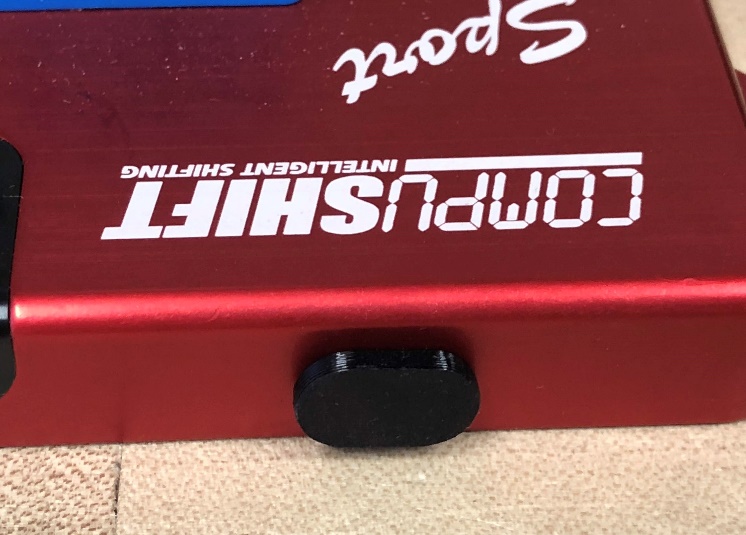
There’s a small pinhole in the center of the rear cover that allows a little air flow to equalize pressure inside the case when you go from sea level to higher elevations. Water cannot pass through the Gore-Tex® liner. You can mount the controller with this side down, but do not cover the hole.
The controller is a sealed assembly. Modifying the case in any way (drilling, tapping, filing, painting, etc.) or opening the case voids the warranty.
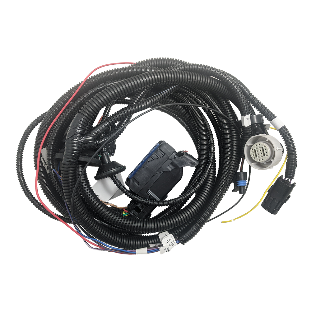
Attach the Main Cable Assembly
The main harness assembly includes all the cables needed for most applications – as well as some you may not use. For those cables not in use, leave them in place and secure the stripped end with insulating tape.
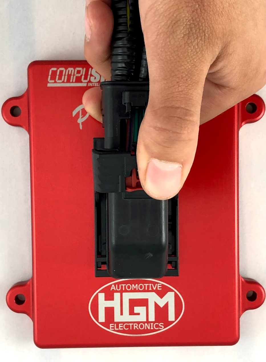
With the cable tail aligned as shown below, carefully align the connector to the 80-pin assembly on the controller.
Press in place, then pull the lever down until it snaps in place.
Push the red tab down to lock.
To remove the connector, pull the red tab up, then press down on the release panel.
Pull the lever up to the unlocked position.
Gently remove the connector from the 80-pin assembly.
Connect the Transmission
For easy identification, all connectors are labeled. Safely route the harness AWAY FROM the exhaust system, the rotating drive shaft, or other moving parts of the drivetrain.
Connect the Main Transmission / Valve Body Plug
Connect the main transmission plug to the corresponding plug on the transmission.
The location will vary depending on the transmission.
Connect the Transmission Output Speed Sensor (TOSS)
Choose the correct TOSS adapter for your transmission and connect it to your vehicle’s sensor.
Connect the Transmission Input Speed Sensor (TISS)
If your transmission has a TISS, connect the mating plug on the harness.
Note that some GM harnesses fit multiple transmissions, so your loom may have a TISS plug even though your transmission does not have a TISS sensor. In this case, tie the unconnected plug safely out of the way with a cable tie; do not connect it.
Connect the Lever Position Sensor
Some transmissions, including Ford and Nissan, require an additional lever sensor connector.
Connect this sensor to the supplied plug on the harness.
Connect the Speedometer / Reproduced TOSS Signal
Use the purple/white wire labeled “SPEEDO OUT” to connect to your vehicle’s speedometer or engine ECM.
DO NOT connect to your original TOSS wires!
On GM vehicles, you can patch this connection to the cable that originally connected to the TOSS. GM does not make a plug and cable to fit, so you must patch the wire directly.
4WD Only: Connect the Transfer Case Low Range Calculation Wire
On four-wheel-drive vehicles, connect the transfer case switch to the yellow Transmission Wiring Harness wire labeled “TRANSFER CASE.” During setup, you will enter the transfer case ratio into the COMPUSHIFT app so it will operate correctly in the LOW Range.
Install the Throttle Position Sensor
You can skip this step if your engine management system connects to the COMPUSHIFT with a CAN bus harness.
Most Common Carburetors
Vehicles with Edelbrock AFB, Holley and Rochester Quadrajet carburetors without existing TPS usually use the Acculink TPS kit. If you are installing AccuLink TPS, go to our website for a step-by-step video. You’ll also find a printed installation guide with your AccuLink TPS kit. If you are reading this document online, you can go directly to the install guide here: Acculink Throttle Position Sensor Installation Guide
Engines with Electronic Fuel Injection (EFI) or an existing TPS
Most engines with Electronic Fuel Injection (EFI) don’t require a separate TPS. In this case, connect the OEM wiring harness using the HGM TPS adapter supplied with your kit as follows:
GM Style TPS
Use the Y adapter if your fuel-injected engine uses the standard General Motors TPS socket.
Other Systems
Use the bare pigtail adapter harness to connect the TPS signal and ground wires to any other type of TPS.
Other Engines
Install cable-operated TPS on vehicles without EFI that are not compatible with AccuLink TPS. Consult with HGM or your dealer before making this purchase.
Connect the Engine, Power and Accessories
Before connecting connecting any wiring in the vehicle, DISCONNECT THE BATTERY.
Any wires or connectors that are not in use, including the optional ones listed below, should be left in place and secured. Stripped ends should be covered with electrical tape or shrink sleeve.
Follow the harness labels and directions below to make the required connections.
Connect the Power, Ground, and Other Wires
From the harness assembly:
Connect the purple/white wire marked “SPEEDO OUT” to the speedometer.
Connect the black wire marked “GRND” to a good ground, preferably at the battery or frame.
Connect the brown wire marked “TACH IN” to either the tachometer output of an electronic ignition system (for example, an HEI), or the tachometer output of an MSD ignition system. This usually won’t be necessary if you are using CAN bus.
Connect the red wire marked “+ 12 SWITCHED” to a circuit that’s powered when your ignition switch is turned to the “ON” position – NOT accessory “ACC” position (min. 6 amps of current).
It is vital that the COMPUSHIFT be on the same switched power as the engine management system, especially if you are using a CAN bus connection. This ensures that CAN bus communication between the two systems occurs in the correct sequence at startup. Failure to do so can result in trouble codes or a failsafe condition on the COMPUSHIFT controller.
Optional: Connect the Throttle Position Sensor
If your system uses a TPS, then attach the connector marked “TPS” to your vehicle’s AccuLink TPS, EFI TPS adapter, or Cable TPS system.
Optional: CAN Bus Connector
Certain versions of the HGM software can obtain throttle position, engine speed, manifold pressure, manifold temperature and other information directly from the ECU through the CAN bus. If applicable, connect the plug marked CAN to your vehicle’s ECM.
Optional: Connect a Mode Switch and Mode LED
Most harnesses are equipped with wires for a mode switch and mode LED. This allows you to change between two preset calibrations, “A” and “B”, on the controller by pressing a pushbutton. The pushbutton should be a momentary switch to ground. The mode LED wire provides current limited power to an LED when the system is in the “B” mode. See the section below on “Using Optional Features” on how to use the switch.
Optional: Connect an Overdrive Cancel Switch and LED
Depending on the transmission type, some harnesses are equipped with wires for an overdrive cancel switch and overdrive cancel LED. An LED connected from the OD CANCEL LED wire to ground will light when the overdrive function is cancelled. The overdrive cancel switch is usually wired as a momentary switch to ground but can be configured as a toggle switch instead. See the section below on “Using Optional Features.”
Optional: Connect a Manual TCC Switch and TCC LED
There is an optional connection for a pushbutton switch to manually engage the torque converter clutch, and an LED to indicate that the TCC is on. This wire may or may not be present in your harness, depending on the type. The switch and its LED can be added later as an accessory. See the section below on “Using Optional Features.”
Regarding Optional Pushbutton Switches
HGM sells three optional stainless-steel accessory switches to complement your application: A/B Mode, Manual TCC, and Overdrive Cancel.
To install one of these switches:
Locate a position that is easy to reach from the driver’s seat.
Drill a 19mm or 3/4” hole for the switch.
Install the switch from the front with the O-ring in place.
Install the nut on the rear of the switch. Tighten gently.
Optional: Connect the Switch-Shift Harness
For vehicles with paddle shifters or pushbutton shifters, an optional Switch-Shift Harness connects to the main connector. For vehicles with paddle shifters or pushbutton shifters, a separate Switch-Shift Harness connects to the wires on the harness. This harness will usually have a separate install guide.
HGM also sells the Twist Machine paddle shifter, shown below.
Optional: Connect the Display
If your system came equipped with a display, use the provided USB micro to USB adapter to connect the display to the USB port.
If you aren’t using a display or other USB accessory, plug the USB port with the dust cover provided in your small parts kit as shown:
Pair and Complete Setup
Do a final check before you proceed:
Recheck all wires and routing for safety, and ensure cables are clear of exhaust and sharp edges.
Reconnect the vehicle’s battery and turn the ignition switch to first position to deliver power to the controller – BUT DO NOT START THE ENGINE.
Confirm that the status LED on the COMPUSHIFT controller is blinking.
Pair Your Device
Reconnect the vehicle’s battery and set the ignition to “ON” to power to the controller.
Be sure Bluetooth is enabled on your smartphone, and then start the COMPUSHIFT Setup app.
The screen should show the serial number of your controller in the list of devices.
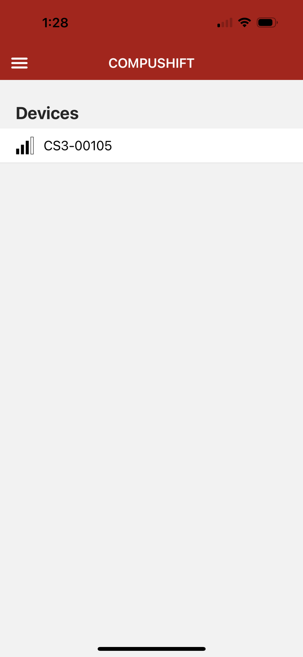
Select that device, and the app will ask to pair with the controller.
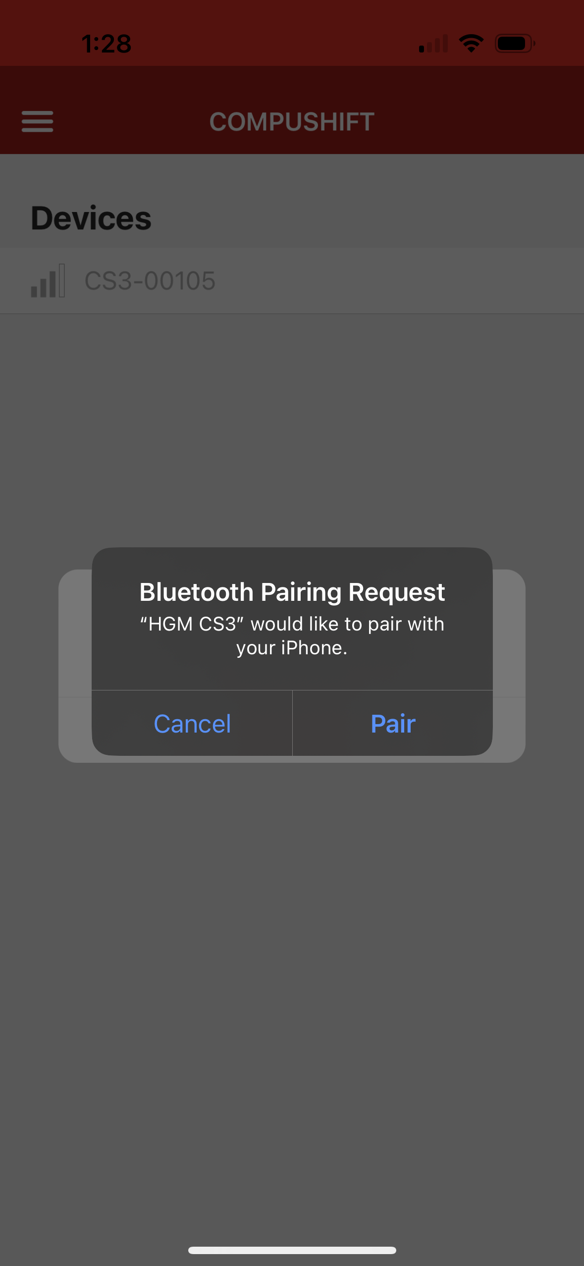
Allow the pairing to complete. The application will now display the home screen.
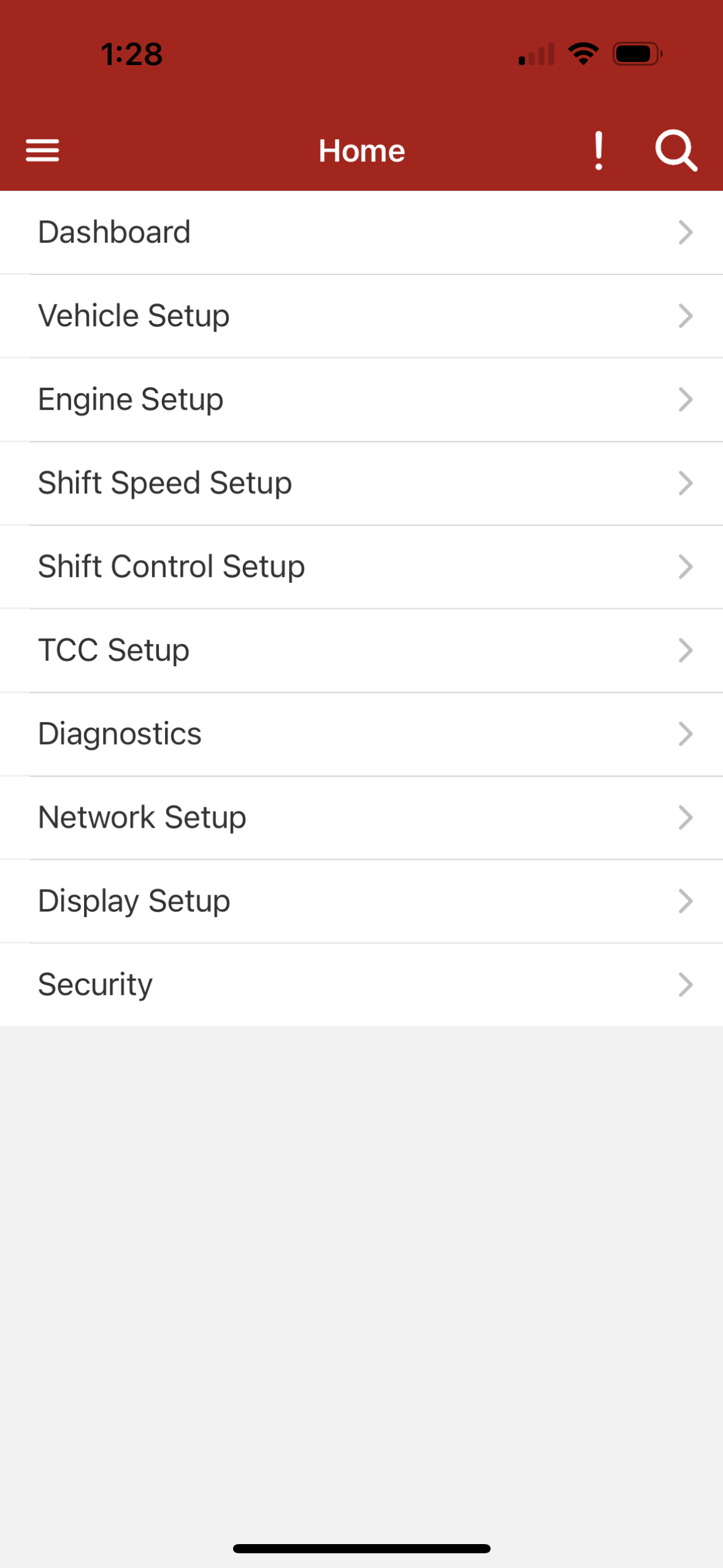
Complete Setup in the App
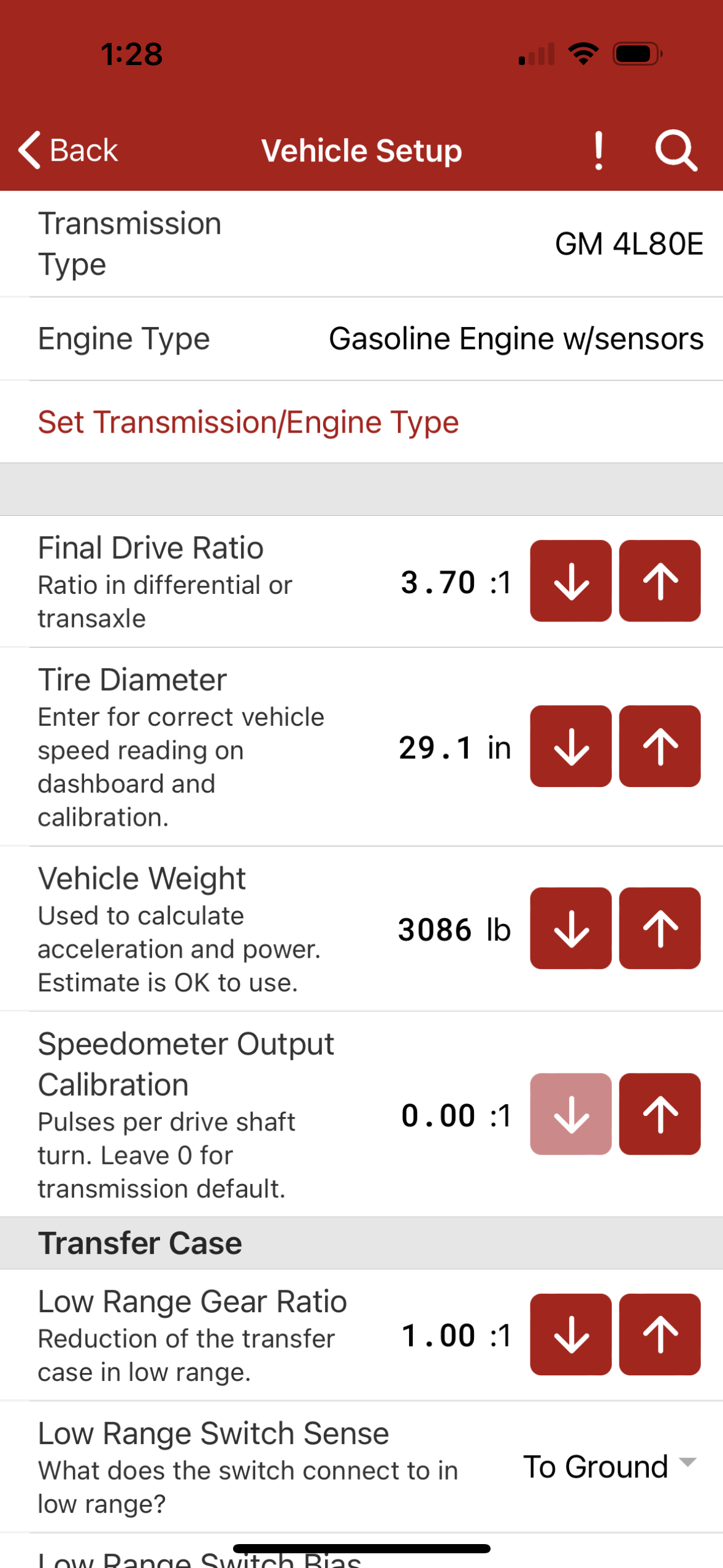
From the home screen of the app, select Vehicle Setup.
From this menu, confirm that the transmission and engine type are correct for your vehicle.
Also verify:
Final drive ratio
Tire diameter
Transfer case ratio (if you have a 4WD vehicle)
Adjust these settings to match your vehicle as needed.
Use the Back arrow to return to the Home page.
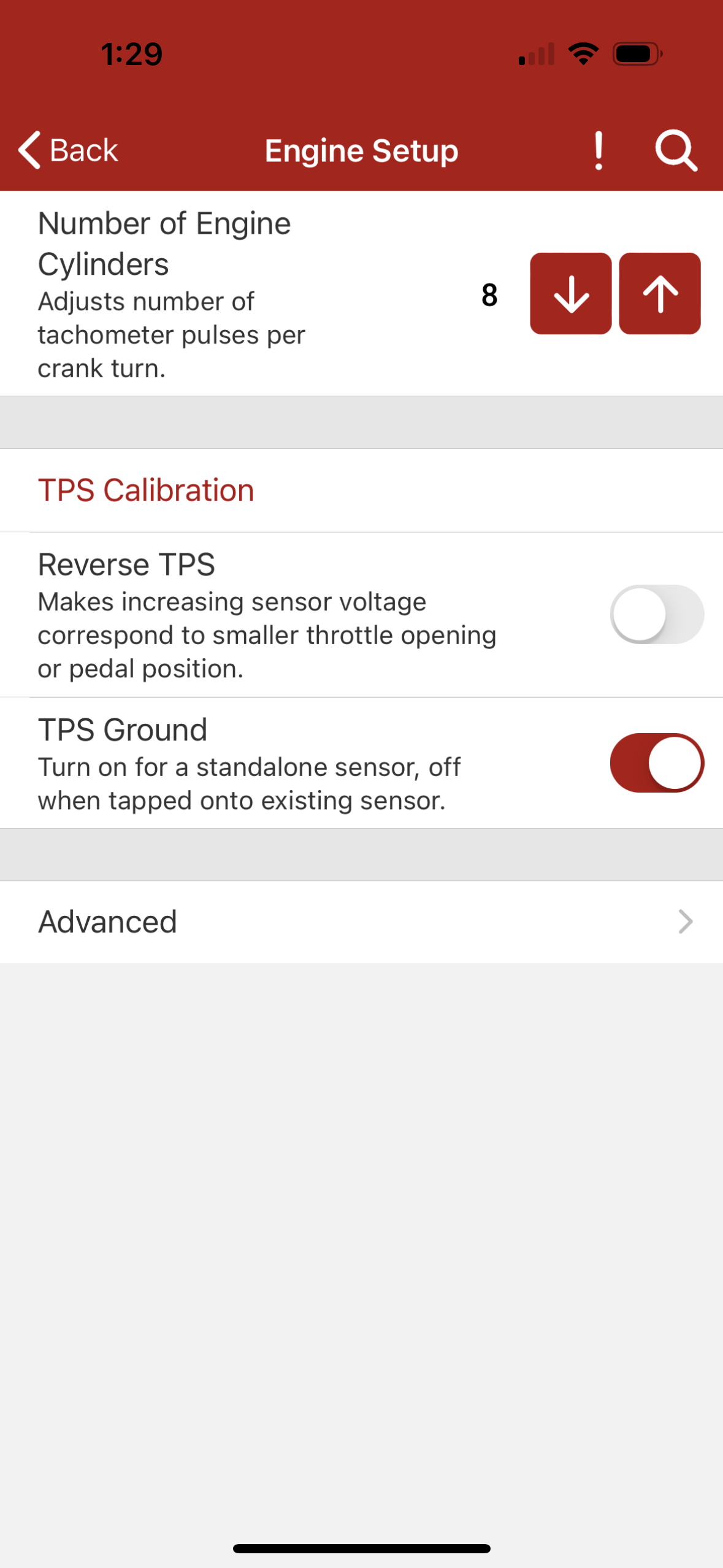
Select Engine Setup.
From this menu, confirm that the Number of Engine Cylinders matches your engine; adjust if necessary.
For some engine types, the cylinder count will not appear.
Use the Back arrow to return to the Home page.
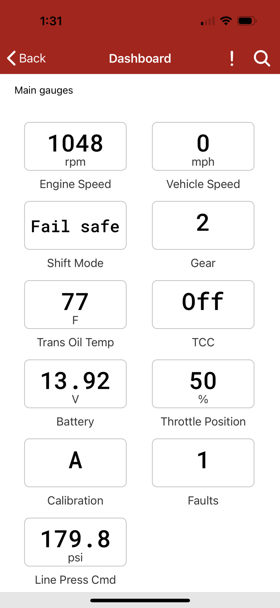
Select Dashboard.
With the gear selector in PARK, start the engine.
Confirm that the engine tachometer reading corresponds to the Engine Speed gauge on the app.
Allow the engine to idle and warm until it normalizes rpm from fast idle or choke.
Turn the engine OFF.
With the gear selector in PARK, turn the ignition switch to ON to power the controller. Wait 5 seconds.
Until you have calibrated your TPS (next step), your controller may show that it is in “Fail Safe” as shown here. This is normal.
Throttle Position Sensor Calibration
If you are using a CAN bus connection to your engine management system, you can skip this section.
We suggest you read this section completely before trying to do the calibration for the first time.
You must to do the calibration with the ignition switch on, but the engine not running.
In the app, return to the Engine Setup menu.
If you are using an Acculink TPS or standalone TPS, turn on the TPS Ground.
If you are using a tap loom to an existing TPS on an engine management system, turn the TPS Ground off
To start TPS calibration, select TPS Calibration from the Engine Setup menu.
The center readout is a digital voltmeter showing the voltage coming from the throttle position sensor.
Ensure that as you press the accelerator pedal, this meter moves up and down. If so, you should be ready to calibrate.
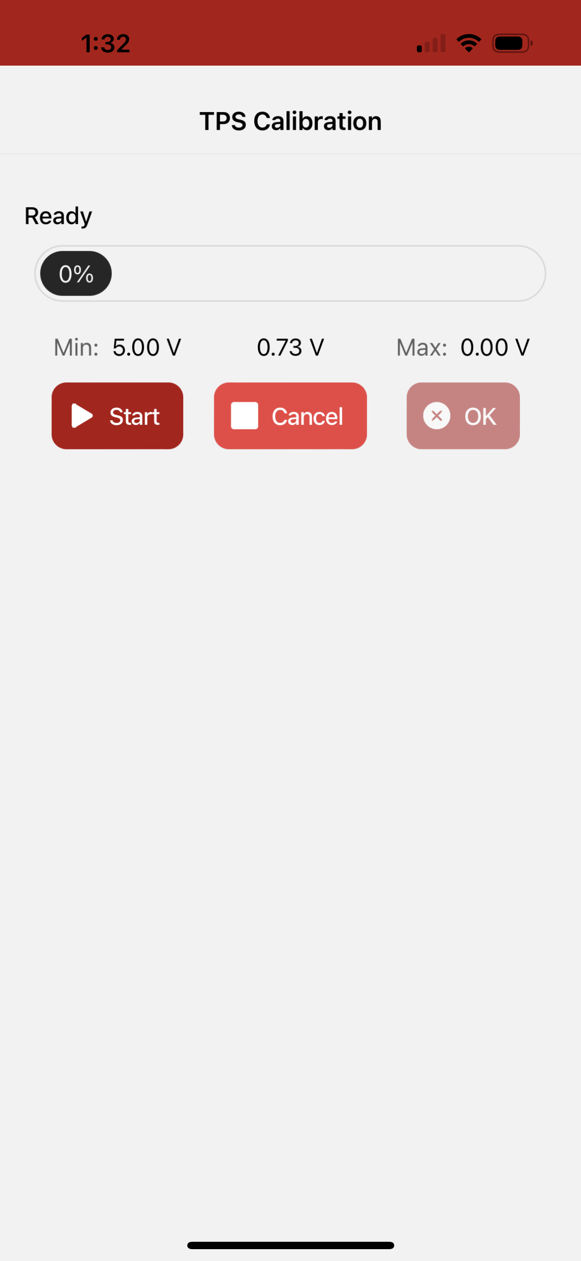
Tap the Start button, then slowly and evenly depress and release the throttle pedal.
Be sure to press the accelerator pedal completely to the floor and then remove your foot.
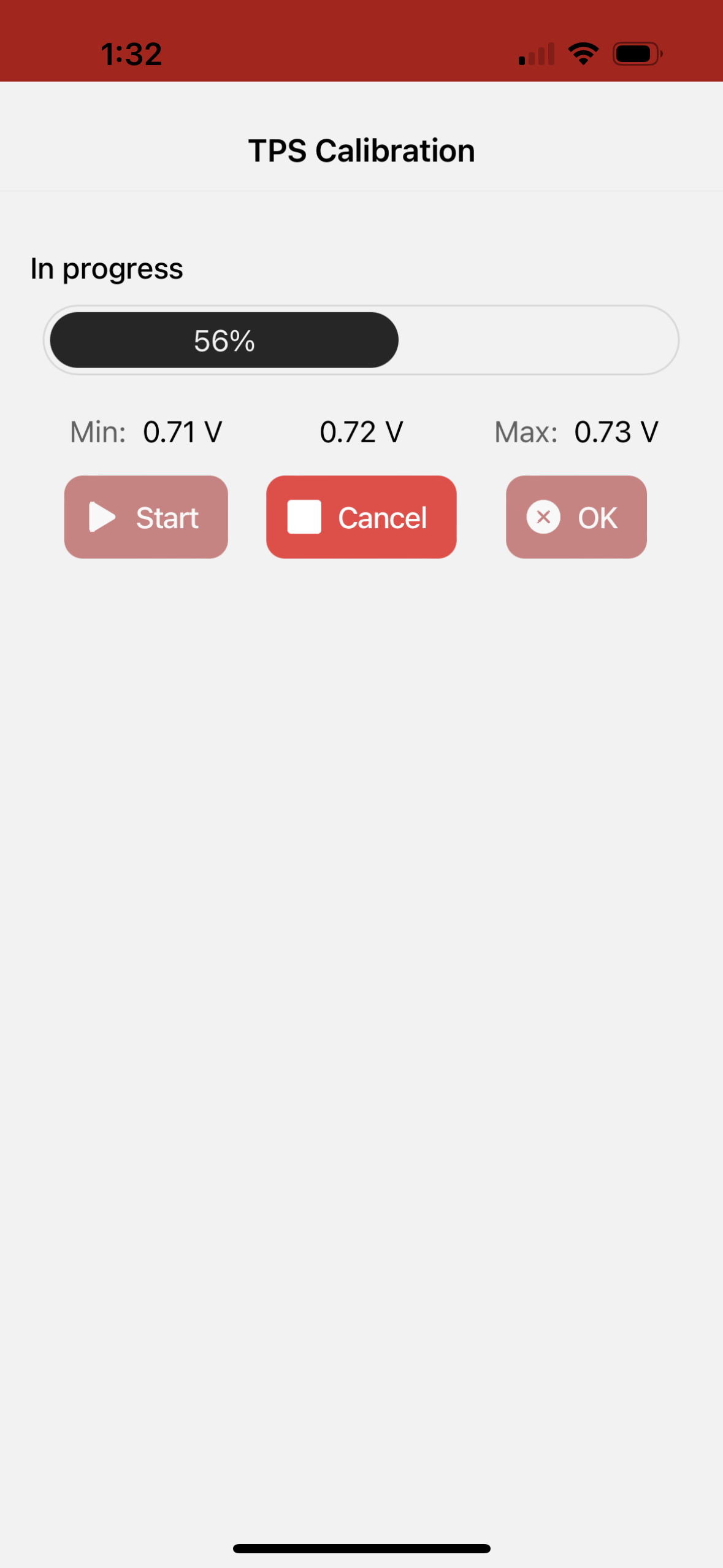
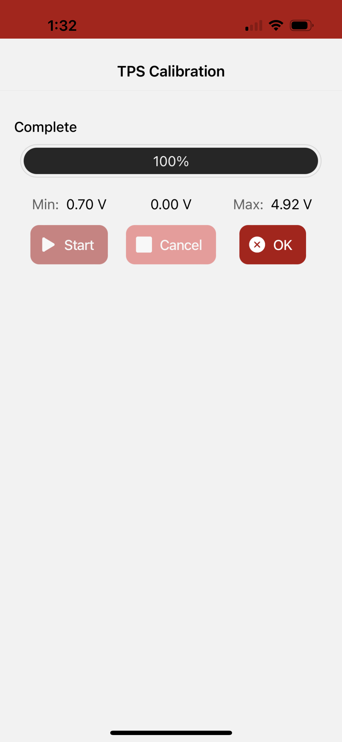
You have 5 seconds to complete this operation, during which time, the progress meter at the top of the screen will move from 0% to 100% as shown.
When the TPS Calibration completes, press OK.
Use the Back arrow to return to the home page.
Final Checks Before You Drive
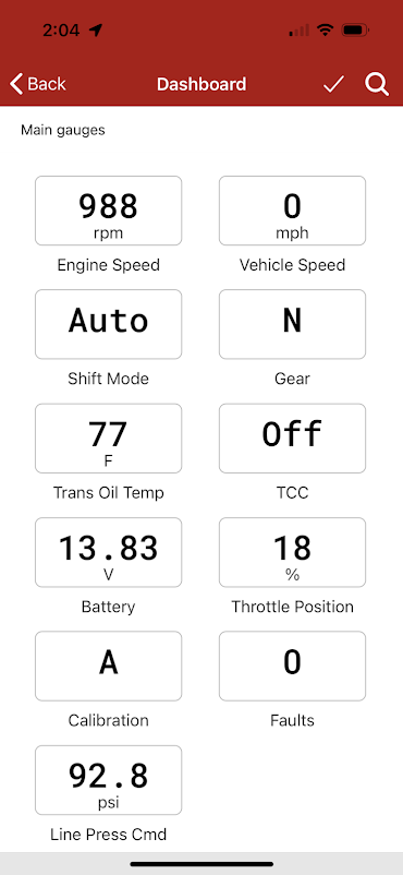
Select Dashboard from the home screen.
When you press the accelerator pedal, the Throttle Position gauge should smoothly change from 0% to 100%.
Start the engine. With the engine running, Engine Speed should be reporting engine speed correctly.
Confirm that the Faults gauge reads “0” (no faults), and the GREEN status light on the controller is blinking slowly. If so, you should be ready to drive.
If there are faults, select Trouble Codes from the Dashboard. From there, choose the DTCs screen and find the source of the problem. Use the Clear Codes button to reset any stored trouble codes.
Road Test!
Now for the test drive! COMPUSHIFT uses information about throttle position, vehicle speed and gear lever position to shift for precision performance.
Some things to keep in mind:
Under light throttle, upshifts occur relatively early.
As throttle position increases, upshifts occur at increasingly higher vehicle speeds.
Under full throttle, upshifts occur at a higher vehicle speed and engine RPM.
A firm shift is required to prevent slippage when the engine is making more torque, so shift firmness is related to throttle position or engine load, rather than vehicle speed. Under less power, the shift can be gentler.
You can adjust the overall shift firmness by changing the “Pressure Adjust” on the main dashboard screen.
You can adjust the overall shift speed by changing the “Shift Speed Adjust” on the main dashboard screen.
Using Optional Features
A/B Mode Switch
If you installed an A/B Mode switch, you may toggle between calibration A and calibration B by holding the button down for 2 seconds.
Note that you can also switch between the A and B calibration through the buttons on the setup app Dashboard screen.
Overdrive Cancel Switch
Overdrive cancel switches can be configured for toggle or pushbutton operation, depending on your switch. Make changes in the Vehicle Setup / Transmission Options menu.
Manual TCC Switch
The torque converter clutch (TCC) can be manually engaged with a single press of the manual TCC switch. A second press reverts to automatic operation. Moving the shift lever also cancels manual TCC operation.
Note that there is no stall prevention when the TCC is manually engaged. If you slow enough with the TCC locked, you will stall your engine.
Paddle Shifter or Shift Up / Shift Down Switches
Normally when you place the shift lever in the Drive position, the COMPUSHIFT will automatically shift. Pressing either the shift up or shift down paddle or switch will change the system to manual operation and will shift up or down accordingly. The transmission will not shift automatically in this mode.
Holding either switch for 2 seconds or moving the shift lever will resume fully automatic operation. The app will indicate the shift mode as “Switch” when the paddle shifter mode is active.
Typical Wiring Diagram
This diagram shows a typical installation, but may or may not be appropriate to your vehicle and transmission.
