
COMPUSHIFT Sport Nissan RE4 Connector Kit 35611 Splicing Instructions
Overview
Please note these are the instructions for installing part number 35611 which mates with harness 35610. These harnesses and parts use Aptiv GT-150.
To complete this successfully you will need the appropriate wire crimping tool, please refer to the back of these instructions for visual references of the style of crimper required (such as Delphi 1424b) and the method to crimp each terminal correctly.
Please read through all of the instructions carefully before proceeding. If any of the information does not appear correct or the diagrams don’t match your vehicle, please contact HGM.
Please note - there are also extra terminals in each packet, please take your time and understand the crimping process prior to attempting to use the pins as they are single use and will have to be cut off if incorrectly connected.
Hot engines, transmissions and exhausts can cause serious injury. Before accessing the appropriate connections allow sufficient time for the engine and transmission to cool.
RE4 Transmission
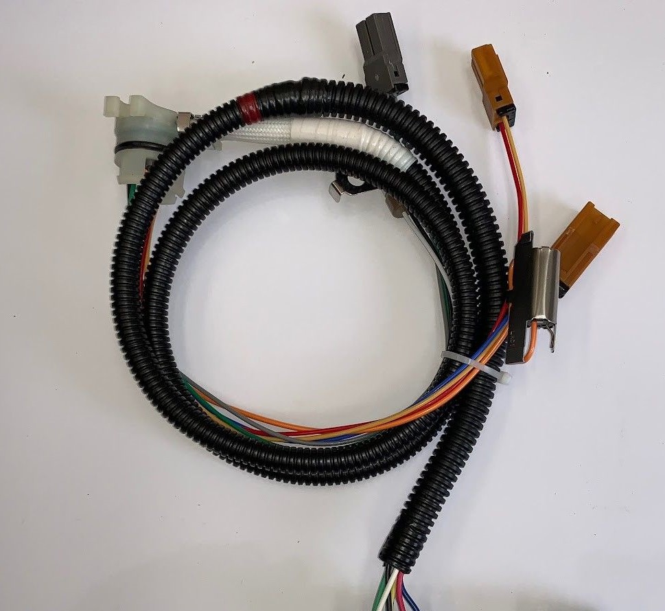
Review the pictures below to identify the components you will be working with.
Pictures may vary due to differences in connectors and transmissions, and should be used for reference only.
Sensor Locations
Internal Loom Lever Switch
Output Speed Sensor
Connector Installation
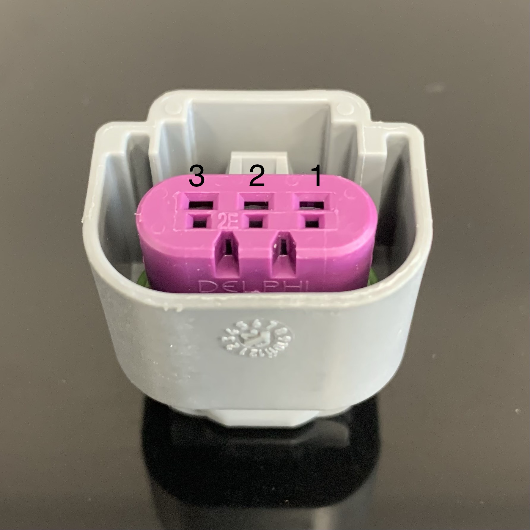
Output Speed Sensor
The output speed connector will require three wires to be installed in the provided 1x3 connector, identified by the gray connector housing and purple secondary lock.
Refer to the splice table below.
WIRE COLOR | CONNECTOR PIN LOCATION |
|---|---|
RED | 1 |
WHITE | 2 |
BLACK | 3 |
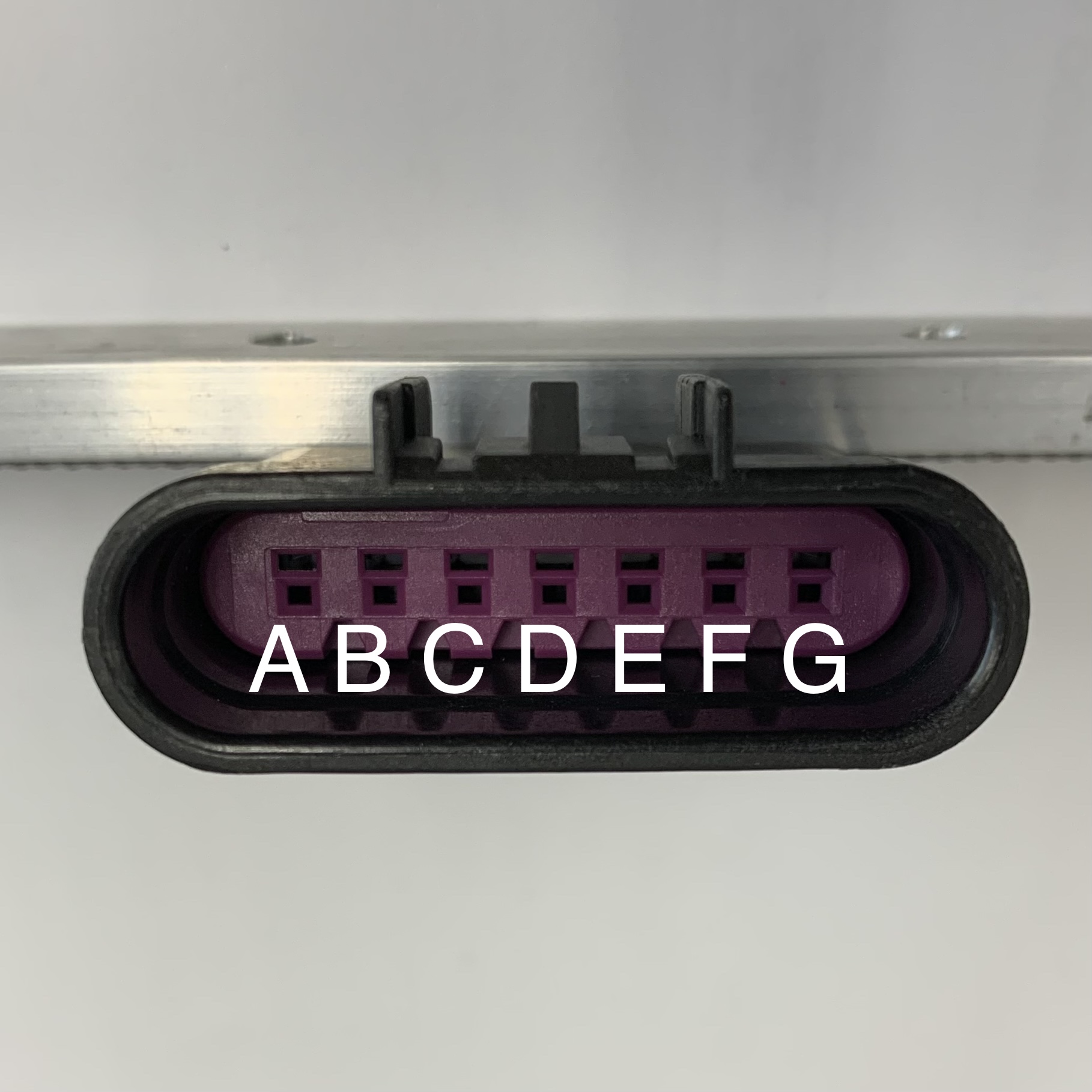
Internal Loom
The RE4 Internal Loom requires splicing of 7 wires. These wires feed the temp sensor and solenoid connections. Refer to the splice table below.
WIRE COLOR | CONNECTOR PIN LOCATION |
|---|---|
GREEN | A |
YELLOW | B |
GREY | C |
BLUE | D |
PINK | E |
BLACK | F |
WHITE | G |
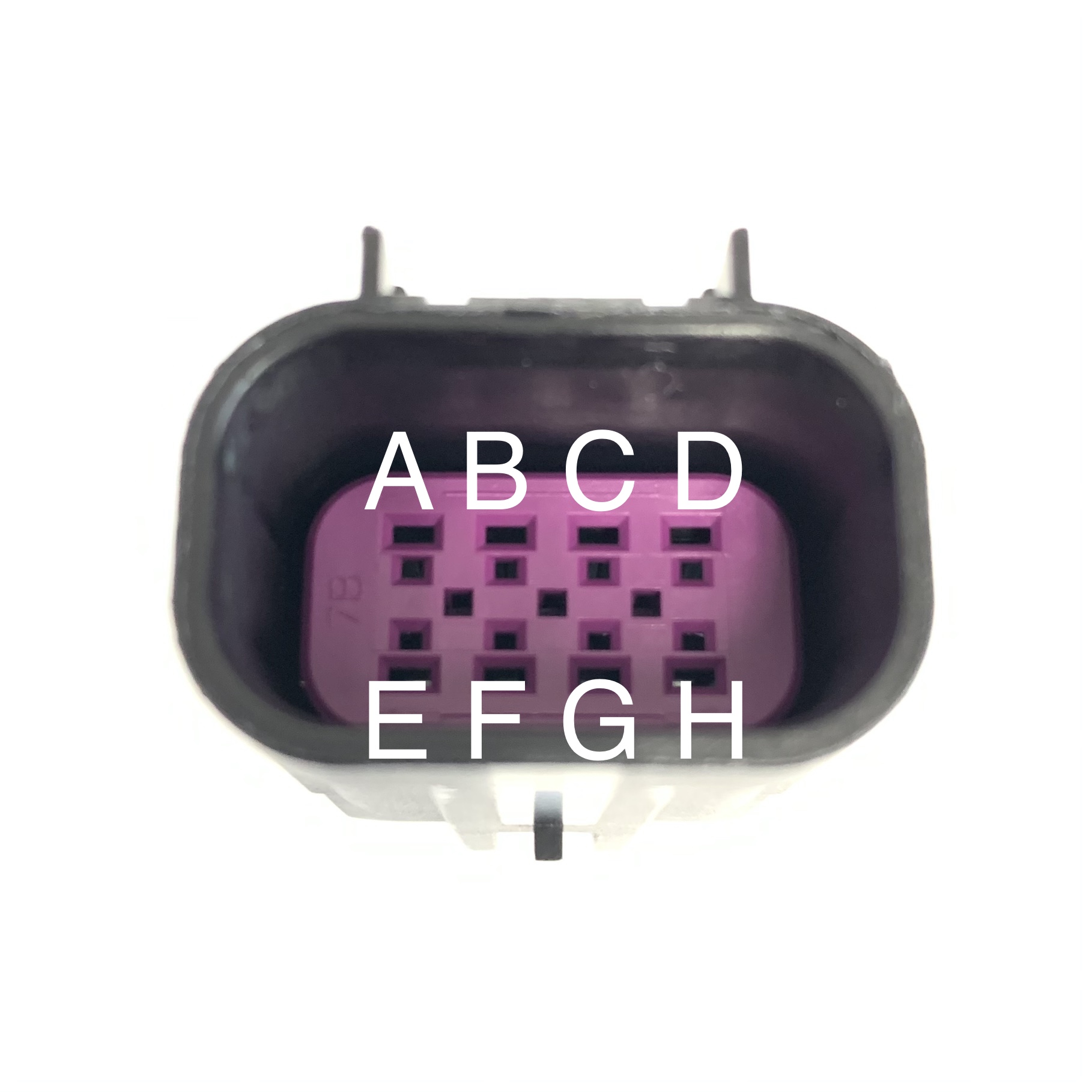
Shift Lever Switch
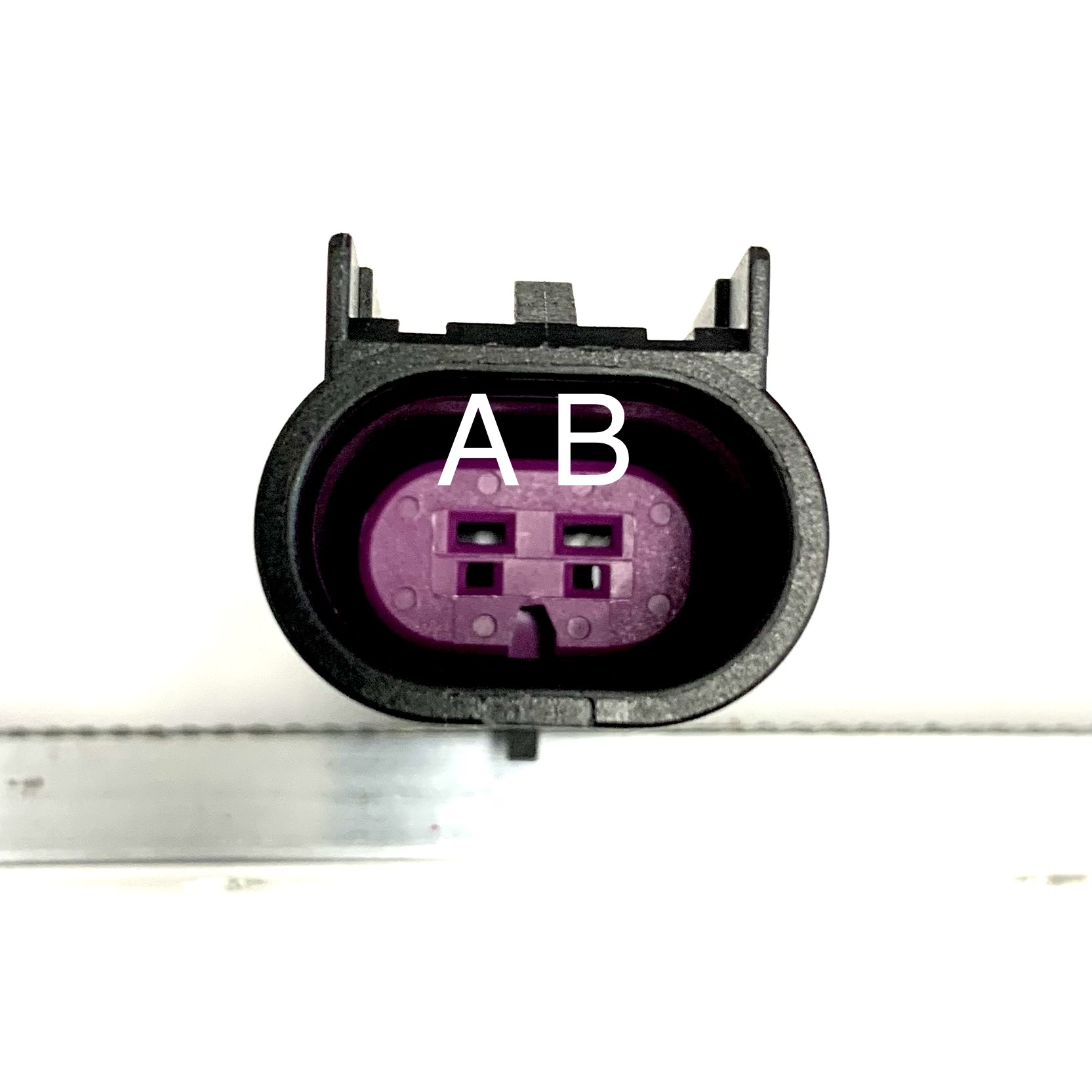
The Shift Lever Switch wiring has two connectors to install, one 2 pin connector for the larger gauge wires and another connector for 7 of the smaller gauge wires.
WIRE COLOR | CONNECTOR PIN LOCATION |
|---|---|
BLACK | A |
BLUE | B |
GREEN | C |
BLANK (USE CAVITY PLUG PROVIDED WITH CONNECTOR) | D |
WHITE | E |
YELLOW | F |
RED | G |
ORANGE | H |
WIRE COLOR | CONNECTOR PIN LOCATION |
|---|---|
ORANGE | A |
BLACK | B |
Crimping the Wires
EXAMPLE WIRE CRIMPERS (Aptiv 1424B in photos)
CRIMPING PROCESS
Stripped wire with seal applied. Place the water and dust grommet over the exposed wire.
Using wire strippers, remove 5mm / .25” of insulation
Secure the pin (remember to identify male and female depending of which side of the connector you’re working on).
Crimp the forward terminal clamps over the exposed wire (do not crimp over the insulation).
Crimp the rear clamps over the water and dust grommet, ensure the tabs fold over each other when applying final pressure.
Confirm the forward clamps are folded securely over the internal wiring and the rear clamp has secured both the weather grommet and the wire’s sheath.
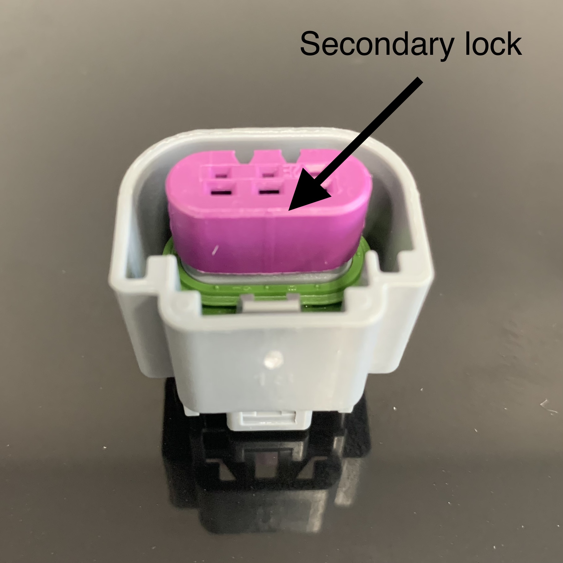
Insert the crimped wire into the appropriate locator (see reference tables). You will hear a click when the pin is correctly seated. Note that the terminal pins are keyed and will only enter the cavity in the appropriate orientation. Conduct a pull test by lightly tugging backwards on the wire to ensure the pin is secure. Push down on the pink secondary locks to further secure the terminals in the connector cavities.
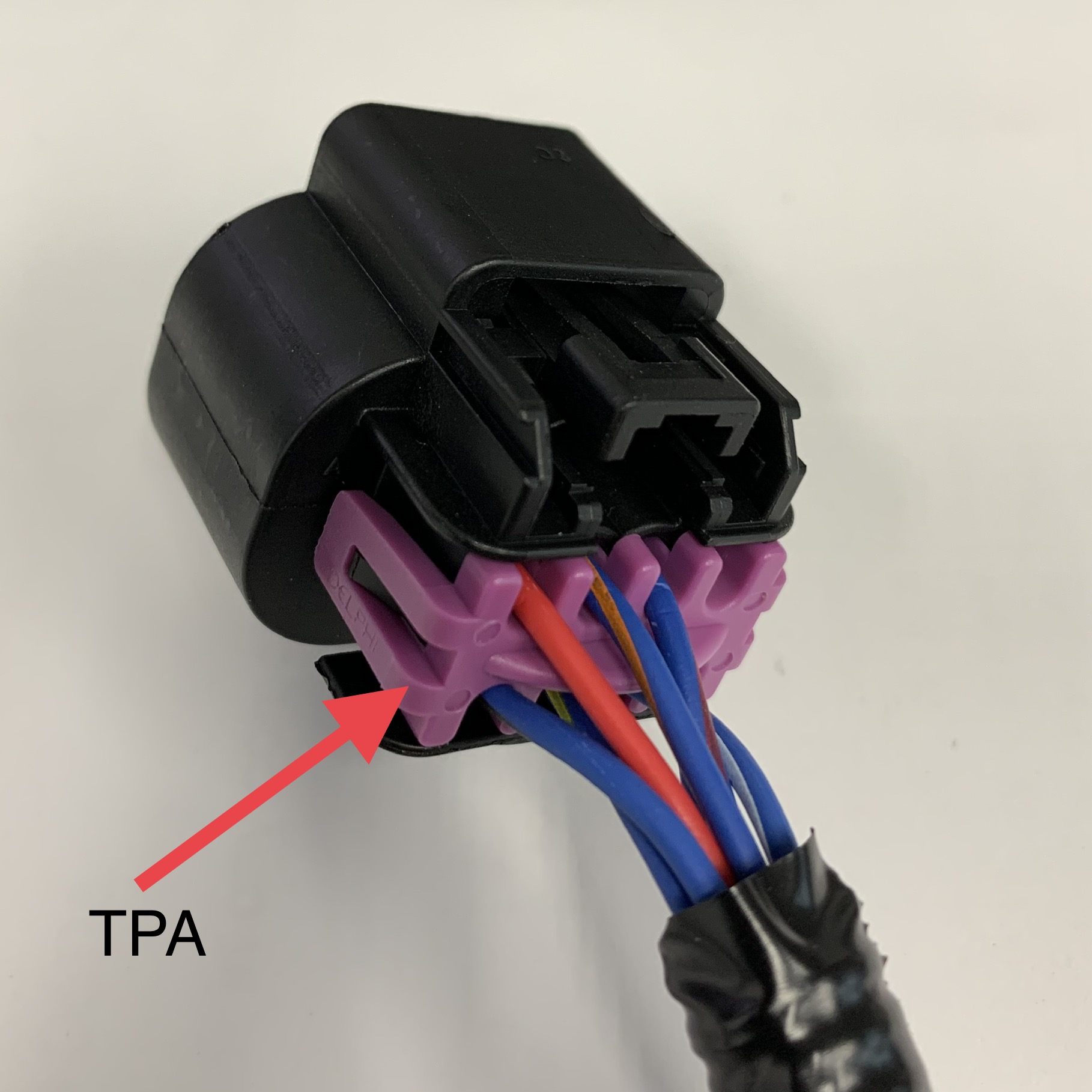
Once ALL pins have been installed, apply the TPA (terminal position assurance) provided with the connector. The connector is now ready to connect with it’s mating connection.