Connecting COMPUSHIFT to Megasquirt
Overview
This article advises how to connect and configure your COMPUSHIFT controller to communicate over CAN bus to a Megasquirt ECU. Depending of the software version, one or more of the the following is monitored by the COMPUSHIFT controller via the CAN bus:
Engine Speed
Throttle Position
Manifold Absolute Pressure
Engine Coolant Temperature
Injector Pulse Width
Air/Fuel Ratio
Ignition Advance
Instructions
CAN bus wiring varies among different Megasquirt ECU’s. The important thing to know is that the COMPUSHIFT does not have internal termination, but is usually shipped with a CAN bus tee and terminator which can be used if it is the last device on the CAN bus. The color codes for the CAN bus wiring on the COMPUSHIFT are CAN High: TAN/BLK, CAN Low: TAN.
Once you have the two systems on the bus, together, configure the software on the ECU’s as follows:
COMPUSHIFT Sport or COMPUSHIFT Pro Setup
Set the engine type to Megasquirt CAN in the Vehicle Setup menu.
Megasquirt 3 ECU Setup
In the Megasquirt setup software, do the following:
Navigate CAN-Bus / CAN Parameters. Set Master enable to “On”.

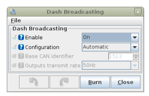
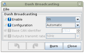
Navigate to CAN-Bus/Dash Broadcasting. Set Enable to “On”. Leave the configuration as “Automatic”.

Be sure to configure the outputs transmit rate for at least 50 Hz.
Megasquirt 2 ECU Setup
In the Megasquirt setup software, do the following:
Navigate CAN-bus / CAN Parameters. Set Master enable to “On”.

Navigate to CAN-bus / Dash Broadcasting. Set Enable to “On”. Leave the configuration as “Automatic”.

Be sure to configure the outputs transmit rate for at least 50 Hz.
Checkout
Restart both ECUs. They should now be communicating correctly. Engine speed and throttle position should correctly show on the CS Setup dashboard.
It is possible for the Megasquirt to report throttle position sensor values below 0% or above 100%. The COMPUSHIFT software will tolerate and clamp values in excess of 5% at either end of the scale without reporting an trouble code, but we recommend having sensor calibrated correctly for best transmission controller performance.
Do NOT drive the vehicle until you have confirmed CAN communications are working properly and you have no trouble codes.
You can diagnose CAN bus problems by going to Diagnostics / Network Diagnostics on the CS Setup App. The CAN 1 Receive Count should be steadily increasing when the ECU’s are communicating correctly. The error counts should always be 0. If you do have errors, do confirm that the CAN bus baud rate is set correctly in Network Setup.
