
Application Notes for Nissan RE5R05A
Internal vs. External Controller
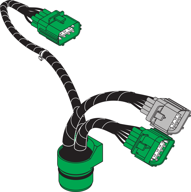
The COMPUSHIFT Pro supports the RE5R05A only with an external / non-mechatronic controller. It's easy to tell the difference between the two by the harness connections. The externally controlled transmission has a harness that looks like this:
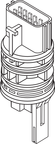
and the internal controller / mechatronic version has a single connector that looks like this on the side of the transmission.
Calibration Notes
Solenoid Pressure to Current Tables
Solenoid Number | Function | Notes |
|---|---|---|
1 | Line pressure | |
2 | TCC pressure | |
3 | Front brake band | |
4 | Input clutch | |
5 | Direct clutch | |
6 | High/Low/Reverse Clutch | |
7 | Low Coast Clutch | Controls line pressure solenoid during low coast clutch application |
Clutch Numbering and Pressure Switches
Clutch | Nissan | Applied | Pressure Switch Input |
|---|---|---|---|
1 | Front Brake Band | 4-5 | SG8 |
2 | Input Clutch | 3-4 | SG12 |
3 | Direct Clutch (Both pistons) | 1-2 | SG10 |
4 | High/Low/Reverse Clutch | 2-3 | SG9 |
5 | Low Coast Clutch | 1st braking, 2nd braking | SG11 |
6 | Direct Clutch (small piston only) | 5-4 | SG10 |
Clutch Application and Release Chart
Motoring Shifts
These shifts are where the engine is providing positive torque through the transmission. With the torque converter unlocked, engine RPM is above the TISS RPM.
Essentially the engine is supplying sufficient torque output to maintain vehicle momentum or more (acceleration)
Shift Description | Mode | Apply Clutch | Release Clutch | Current | Next Gear |
|---|---|---|---|---|---|
Motor Upshift 1 – 2 | Auto | #3 – Direct (Both Pistons) | #4 – HighLow Reverse | F1 | F2 |
Motor Upshift 2 – 3 | Auto | #4 – HighLow Reverse | None / Sprague | F2 | I3 |
Motor Upshift 3 – 4 | Auto | #2 – Input | #1 – Front Brake Band | I3 | I4 |
Motor Upshift 4 – 5 | Auto | #1 – Front Brake Band | #6 – Direct (Small Piston) | I4 | I5 |
Motor Downshift 2 – 1 | Auto | #4 – HighLow Reverse | #3 – Direct (Both Pistons) | F2 | F1 |
Motor Downshift 3 – 2 | Auto | None / Sprague | #4 – HighLow Reverse | F2 | F2 |
Motor Downshift 4 – 3 | Auto | #1 – Front Brake Band | #2 – Input | I4 | I3 |
Motor Downshift 5 – 4 | Auto | #6 – Direct (Small Piston) | #1 – Front Brake Band | I5 | I4 |
Braking Shifts
These shifts are where the is providing negative (braking) torque through the transmission. With the torque converter unlocked, the engine RPM is below TISS RPM.
This will result in the engine providing resistance to slow the vehicle - hence "Braking" shift.
Shift Description | Mode | Apply Clutch | Release Clutch | Current | Next Gear |
|---|---|---|---|---|---|
Braking Upshift 1 – 2 | Sports | #3 – Direct (Both Pistons) | #4 – HighLow Reverse | I1 | I2 |
Braking Upshift 2 – 3 | Sports | #4 – HighLow Reverse | #5 - Low Coast | I2 | I3 |
Braking Upshift 3 – 4 | Sports | #2 – Input | #1 – Front Brake Band | I3 | I4 |
Braking Upshift 4 – 5 | Sports | #1 – Front Brake Band | #6 – Direct (Small Piston) | I4 | I5 |
Braking Downshift 2 – 1 | Sports | #4 – HighLow Reverse | #3 – Direct (Both Pistons) | I2 | I1 |
Braking Downshift 3 – 2 | Sports | #5 – Low Coast | #4 – HighLow Reverse | I3 | I2 |
Braking Downshift 4 – 3 | Sports | #1 – Front Brake Band | #2 – Input | I4 | I3 |
Braking Downshift 5 – 4 | Sports | #6 – Direct (Small Piston) | #1 – Front Brake Band | I5 | I4 |
Notes
Apply pressures for all shifts except 4-5, 5-4 are actually apply rates in kPa/sec or psi/sec. 4-5 and 5-4 shifts are absolute apply pressures and are overlapping shifts.
The large piston of the direct clutch is disabled in 4th and 5th gear, so only the small one is used. The clutch area is the same, so prefill, stroke, and apply pressures must be higher by about 2.6X.
Current Gear and Next Gear columns are for internal software reference purposes only and do not provide the end user with any usable information.
Pressure Switch Monitoring
The clutch pressure switches are monitored and generate DTC's when the system debug level is not 0. In a factory system, these switches are always monitored, but given that some custom valve bodies are built without them, it seemed logical to use them only during calibration when debug is turned on.