
Application Notes for Toyota A750
Sport Shift vs. Gate Shift
The A750 comes in two variations, depending on the vehicle: sport shift and gate shift. There is no way from the outside of the transmission to determine whether it was originally gate shift or sport shift other than to know what shift lever was used with the transmission originally. It is important to know which you have because you can use a sport shift transmission with a gate style shifter, but you can’t use a gate shift transmission with a sport shift type shifter. There is a kit available to convert between the two types.
Identifying Which Type You Have
Method 1 - Identify the donor vehicle
If you know which vehicle was used as the donor for the A750, you can look at the shift lever in that vehicle.
Method 2 - Disable the transmission ECU and move the vehicle in D2
If you have a gate shift transmission fitted to a car with a gate style shifter, you can select D2 even with no power or ECU controlling the transmission. Sport shift transmissions always get D4 in the D position without power or ECU.
Method 3 - Inspect the valve body
We recommend this as a last resort performed by an transmission mechanic.
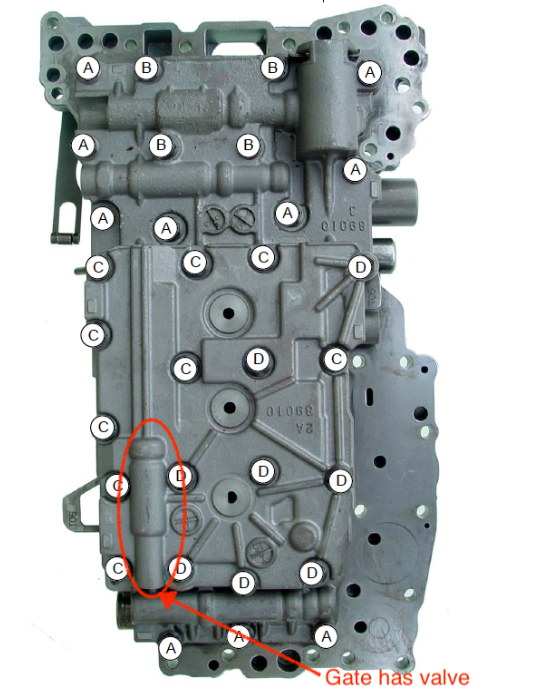
This picture below is the top side of the A750 valve body after it has been removed from the transmission. The valve bore marked in the drawing will have a movable spool valve in the gate shift version of the transmission. This bore is empty in the sport shift version
Gate Shift Overview
The A750 gate shifter has a pattern like this:
PRND-4 31-2
It has the same up number of vertical positions as a Toyota 4 speed shift lever, but the left right movement, which does not move the manual valve on the side of the transmission, is detected by switches for D5/D4 and D1/D2.
Sport Shift Overview
The A750 sport shift lever has a pattern like this:
PRN +D S -
By moving the lever into the S (sport) position, you can manually select gear or range.
Pressure Control Tables
% based pressure upshift control tables are used for accumulator control.
Absolute based pressure control tables are used for braking downshifts, N-1, 4-5, and 5-4.
Clutch Numbering
Clutch | Toyota | Applied |
|---|---|---|
1 | C1 | N-1,N-2,N-3,N-4, 5-4 |
2 | C2 | 3-4 |
3 | C3 | 2-3 |
4 | B1 | 3rd gear braking, 4-5, N-5 |
5 | B2 | 2nd gear braking |
6 | B3 | 1-2 |
7 | B4 | 1st gear braking |
Solenoid Numbering, OEM and DTC Names
DTC Solenoid Name | PWM Driver Number | Toyota Solenoid Name | Function |
|---|---|---|---|
Pressure Control Solenoid A | 1 | SLT | Line pressure control |
TCC Pressure Control Solenoid | 2 | SLU | TCC control |
Pressure Control Solenoid B | 3 | SL1 | C1 pressure control, accumulator pressure control, depending on SR |
Pressure Control Solenoid C | 4 | SL2 | Braking clutch pressure control |
Shift Solenoid A | 5 | S1 | Shift valve control |
Shift Solenoid B | 6 | S2 | Shift valve control |
Shift Solenoid C | 7 | SR | Relay valve control. Switches between having SL1 control accumulator pressure and C1 pressure |
Solenoid Pressure to Current Tables
Solenoid Number | Toyota Solenoid Name | Function | Notes |
|---|---|---|---|
1 | SLT | D1,D2 line pressure | This table is used in R as well, but the valve body adds a 4 bar boost |
2 | SLT | D3,D4,D5 line pressure | |
4 | SLU | TCC Pressure | |
5 | SL1 | C1 Clutch Pressure | SL1 when used to control C1 pressure |
6 | SL2 | B1,B2,B4 Clutch Pressure | SL2 when used to control braking clutch pressure. |
Torque Management Output
Pin 16 on the controller is driven to +12 during shifts and other torque management events.