Install the AccuLink TPS (Optional)
This video explains the complete installation, step-by-step, or you can follow the directions below.
Find the AccuLink TPS Parts
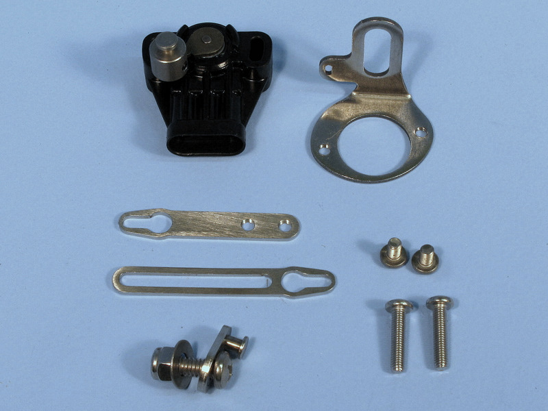
You should have the following parts:
- Sensor bracket
- Ratio arm
- Adjustable arm (2 pieces)
- Two 10/32" x 7/8" Phillips pan-head screws
- Other mounting hardware (stainless steel nuts, washers, brackets and screws)
Assemble the AccuLink TPS and Bracket
- Identify the TPS itself, the sensor bracket and the two 10/32" x 7/8" Phillips pan-head screws.
- Mount the TPS to the sensor bracket with the screws gently tightened. Be sure the plug side of the TPS is vertical (near the bracket mount), as shown.
- Tighten the TPS screws.
Assemble and Install the Ratio Arm
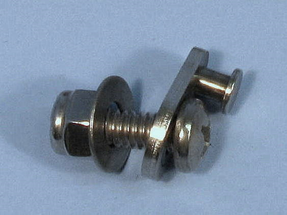
- Find the Ratio Arm from your COMPUSHIFT II Kit. It's the small oval piece of metal (shown here) with a protruding stud on its smaller end.
For Edelbrock AFB or Holley carburetors, remove the inset washer. For Rochester Quadrajet, leave the washer in place.
- Install the Ratio Arm onto the carburetor linkage as shown, using the ¼-20" x 5/8" pan head Phillips screw, washer, and nylon insert lock nut.
- The Ratio Arm is designed to mount in the linkage where a kick-down cable normally attaches.
- The washer sits between the carburetor linkage and the nylon insert lock nut.
Gently snug the screw and nut, but do not completely tighten.
Align the Ratio Arm
Edelbrock AFB & Holley
- Set the Ratio Arm so that the center of its pin is aligned with the edge of the carburetor linkage, as shown.
Tighten the screw and nut in this position.
Rochester Quadrajet
- Set the Ratio Arm so that its pin is vertical.
Tighten the screw and nut in this position.
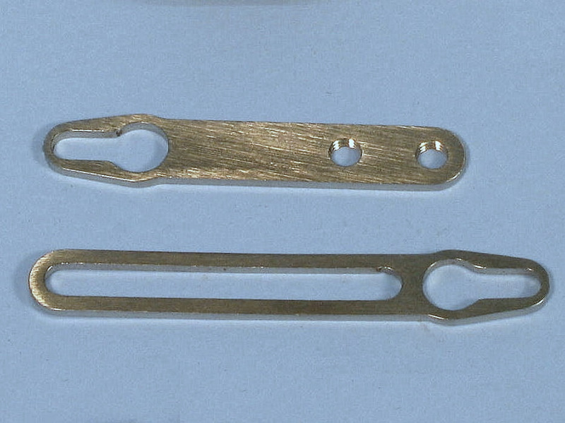
Assemble the Adjustable Arm
The Adjustable Arm from your COMPUSHIFT II Kit contains two (4) pieces:
- Fixed, threaded section
- Sliding section
- Two screws
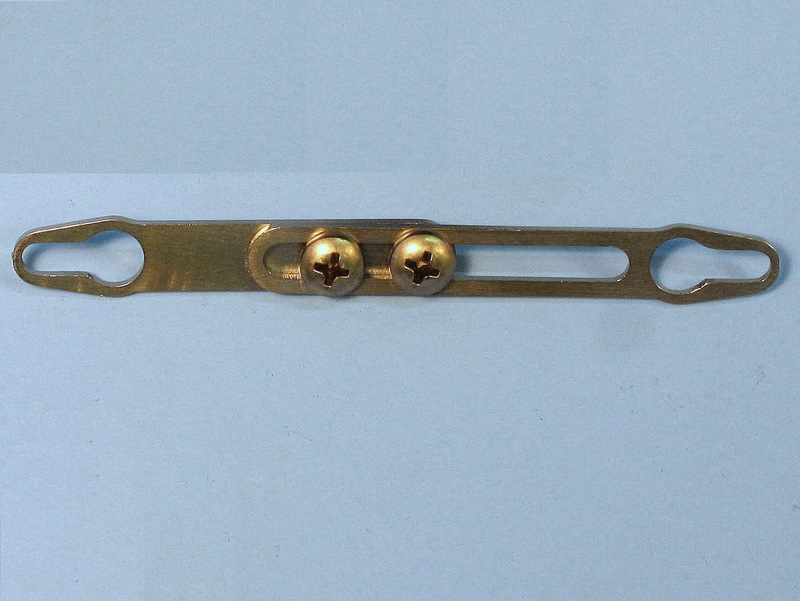
Find and assemble the Adjustable Arm, leaving the screws gently snug.
Attach The Throttle Position Sensor
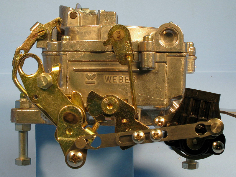
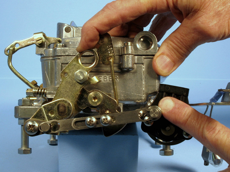
Attach the fully assembled AccuLink TPS to the carburetor using its linkage side-rear manifold bolt.
- The TPS must be aligned correctly: rotation of the throttle linkage should match the rotation of the TPS.
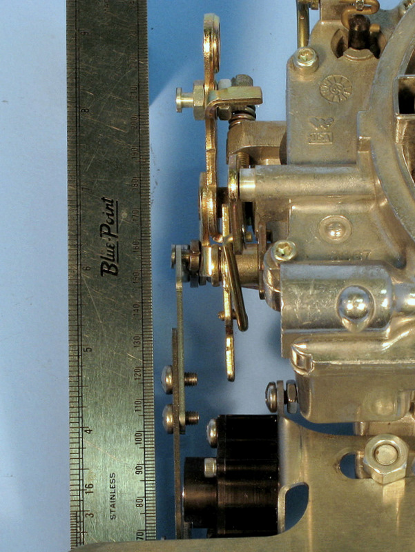
- The Ratio Arm must be aligned along a straight line with the TPS (see photo). Hint: think of self-aligning window louvers.
- A straight edge or ruler can help you with correct alignment.
Set the Adjustable Arm Length
- Connect the fixed, threaded section of the Adjustable Arm to the Ratio Arm.The screw heads should face outward, away from the carburetor.
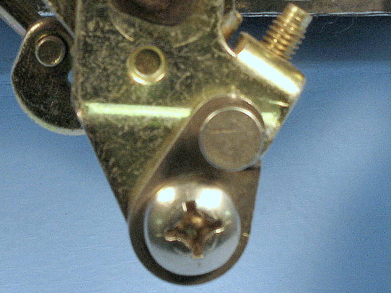
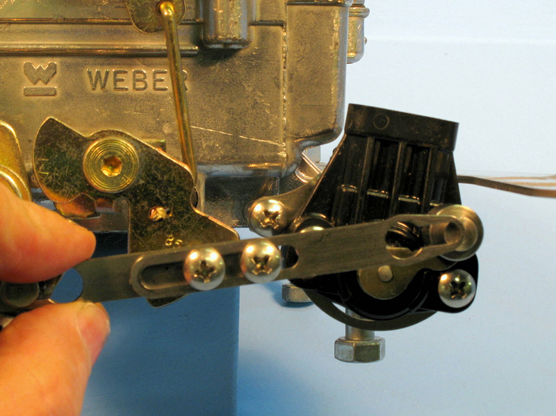
- Adjust the arm length so the edge of the sliding section's slot is aligned with the center of the TPS pin (as shown here) for the correct length.
- Tighten the adjustable arm screws at this position.
- Disable the fast-idle cam for the choke so the carburetor butterflies are on low-speed idle
Install the Adjustable Arm
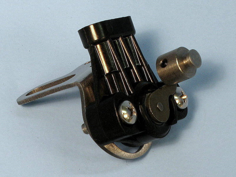
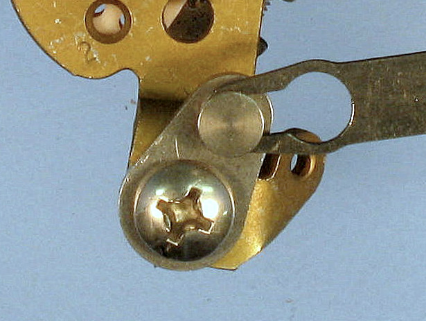
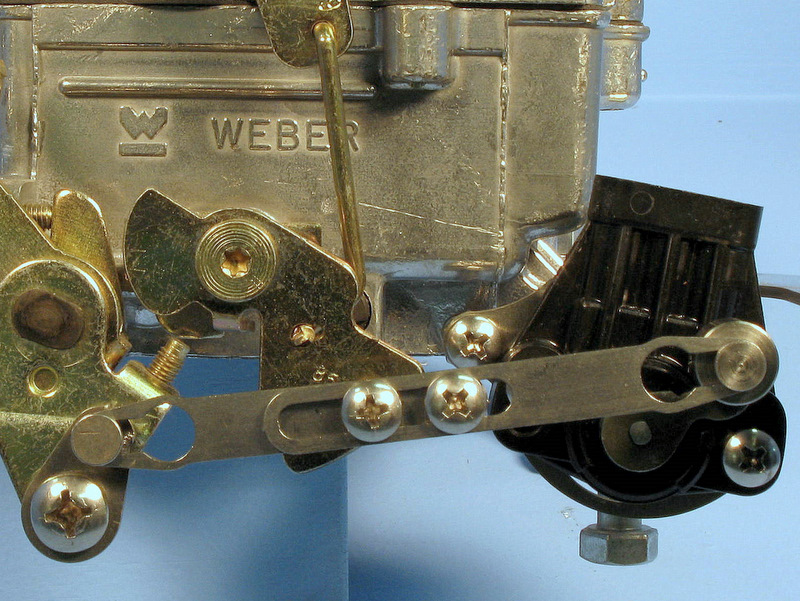
Install the Adjustable Arm by rotating the TPS so its pin can be inserted into the Arm, as shown here in its fully installed position.
Check the Adjustable Arm & TPS
- Check the Adjustable Arm with the throttle fully closed. There should be tension on the arm and no free play.
- Correct any free play by slightly shortening the arm.
- Hold the carburetor linkage in the fully open position. Confirm the TPS has some remaining rotation/stroke by pressing on its arm as shown.
- If the TPS is fully extended (i.e., there is no remaining rotation/stroke), then lengthen the arm slightly to correct.
The TPS should not reach the end of its rotation or stroke in either direction, but be slightly off the stop at each end of its travel. Failure to achieve this could result in poor operation.
Check The Linkage
- Rotate the throttle linkage through its full range of travel to ensure no part of it hits the TPS.
- The position of the TPS bracket must clear the secondary butterfly linkage. This is especially important on the Rochester Quadrajet.
- To ensure smooth clearance, adjust the TPS bracket as necessary.
Do not lubricate the linkage. The AccuLink system is designed to work without lubrication. Most lubricants will attract dirt, shortening the life of the system.
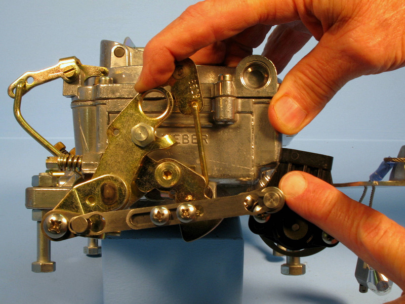
This photo shows an incorrect install: the TPS rotation is not aligned with the linkage, and neither are the arms.
Connect the AccuLink TPS to the Harness
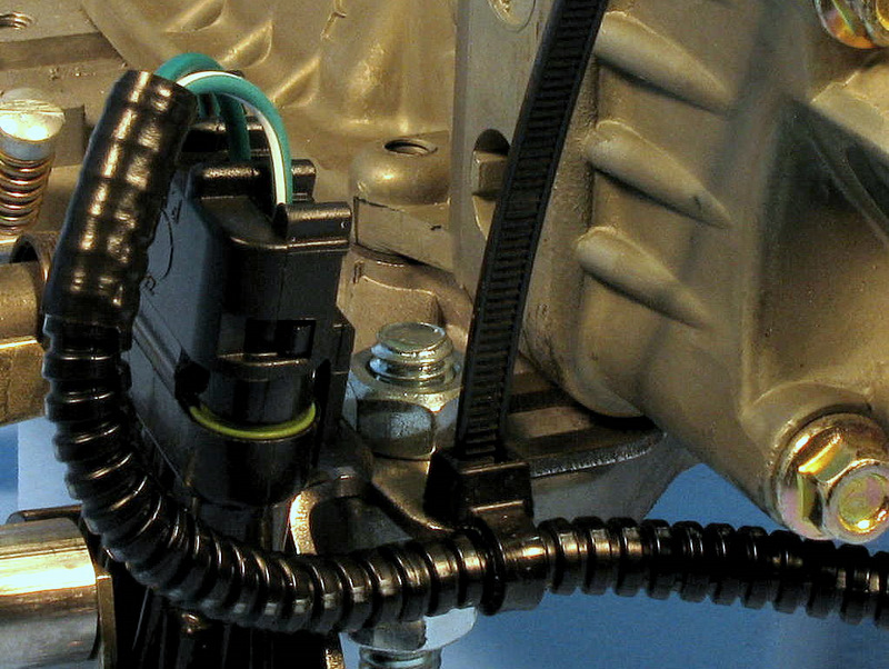
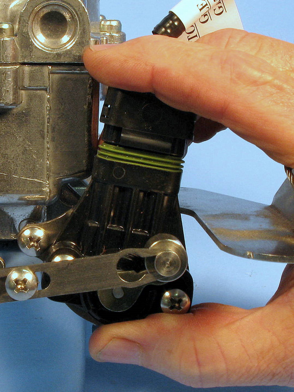
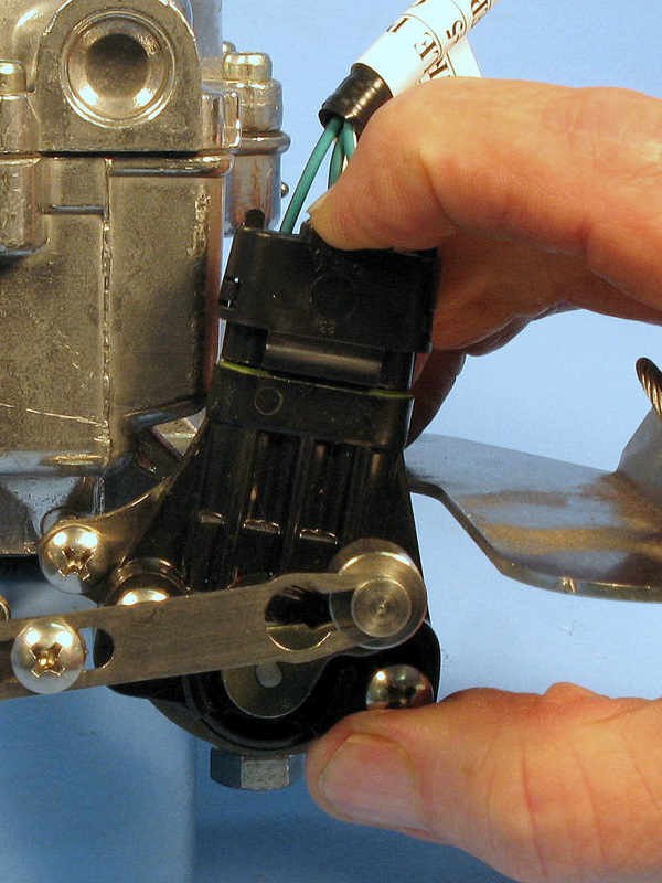
- Snap the TPS plug into the AccuLink TPS. The plug has a rubber gasket that fits tightly.
- Be sure to push the plug fully into the socket by squeezing the plug and the sensor together so you don't bend the sensor bracket.
- This may require two hands.
- If you can see the green gasket (first photo), it is not fully connected. It should be fully compressed (second photo).
Your system may have been shipped with an extension cable to connect the AccuLink TPS to the Controller if it's mounted far from the engine. If necessary, route the extension cable between the COMPUSHIFT II Controller and the TPS.
Secure the Wiring Harness to the AccuLink TPS
- From the bottom, feed the supplied cable tie and insert it through the slot in the TPS bracket.
- Cinch the cable tie around the wiring harness.
- Trim excess tie length as desired.
Be sure to set the TPS Ground setting in the COMPUSHIFT controller to "on" when you are using an existing EFI TPS.