
Installing the AccuLink Refit Kit
Introduction
HGM Automotive Electronics thanks you for upgrading your cable throttle position sensor to the AccuLink TPS system. We believe that great results can be achieved with a very careful installation of the cable operated throttle position sensor. We have hundreds of people (including us!) who use it. However, the cable-operated system can be difficult to get perfect. Some custom fabrication is usually required, and not everybody gets consistently great results.
We studied this problem at length and came up with a solution that fits the most popular carburetors: Holley, Edelbrock AFB, and Rochester QuadraJet. The AccuLink TPS offers the same or better performance with less hassle. It is compact, and has a very direct linkage. Installation and calibration requires a few simple steps and no custom fabrication.
Because the cable system and the AccuLink TPS use the same basic sensor and compatible wiring harnesses, we can offer it as an upgrade. This manual describes the upgrade process.
Installation Planning
This manual assumes that you have an installed and working COMPUSHIFT system. Your system should be using the cable operated throttle position sensor on a Holley, Edelbrock AFB, or Rochester QuadraJet carburetor. AccuLink TPS is not suitable for other systems at this time.
This book describes the process of removing the existing throttle position sensor and replacing it with the AccuLink TPS system.
The old system will be completely removed. Components from the old system will be removed and set aside for use in the new system. The old system will not be reusable when the AccuLink TPS installation is complete.
Required Tools and Supplies
For installation, you will need, at a minimum, the following tools:
- #2 Phillips screwdriver
- Socket / end-wrench assortment
You may also need the following supplies:
- Insulating tape
- Wire crimp connectors
- Wire spade lugs
Removing the Old System

Remove the existing cable bracket, cable end, studs, and linkage plates.
Disconnect the throttle position cable wiring from the sensor box. Remove the box and the cable from the car.
Removing the Sensor

Open the sensor box by removing the four case screws and lid. Lift the cable loop from the sensor and push it forward into the cable housing.
Using a Phillips screwdriver, remove the two screws holding the sensor. Remove the sensor from the case.
Installing the Sensor Pin
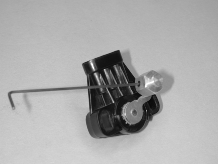
Place the sensor pin over the sensor arm and align the Allen set screw with the flat of the arm.
Tighten the Allen set screw.
Installing the AccuLink TPS
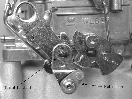
Begin installation by identifying the ratio arm. The ratio arm is a small oval piece of metal with a protruding stud on its smaller end.
If you are installing the arm on an Edelbrock AFB or Holley carburetor, remove the insert washer / knockout. For a Rochester Quadrajet, leave the washer in place.
Install the ratio arm onto the carburetor linkage using the ¼-20 x 5/8 pan-head Phillips screw, washer, and nylon insert lock nut as shown above. The ratio arm is designed to mount in the linkage where a kick-down cable would normally attach. The washer sits between the carburetor linkage and the nylon insert nut as shown on the opposing page. Gently snug the screw and nut, but do not completely tighten.
Aligning the Ratio Arm for Edelbrock AFB and Holley Carburetors
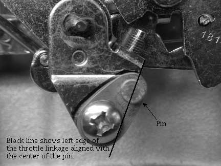
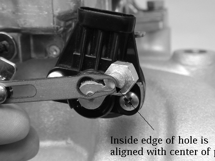
For Edelbrock AFB and Holley carburetors, set ratio arm angle so that the center of the ratio arm pin is aligned with edge of carburetor linkage as shown above.
Tighten the screw and nut in this position.
Aligning the Ratio Arm for Rochester Quadrajet Carburetors
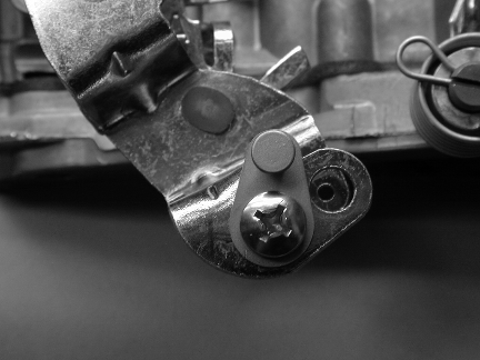
For the Rochester Quadrajet, set the ratio arm angle so that the ratio arm pin is vertical as shown in the picture above. Tighten the screw and nut in this position.
Assembling the TPS Bracket

Identify throttle position sensor, sensor bracket, and two 10/32x7/8 Phillips pan-head screws.
Mount the throttle position sensor to the sensor bracket as shown on the opposing page. Gently tighten the screws gently so that throttle position sensor can be rotated on the bracket.
Rotate throttle position sensor on the sensor bracket fully counterclockwise. The plug side of the throttle position sensor should be vertical. Tighten throttle position sensor screws.
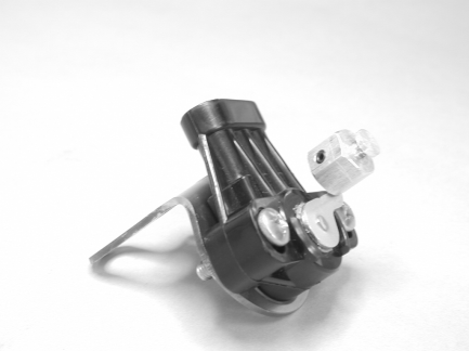
This picture shows the completed sensor and bracket.
Attaching the TPS to the Carburetor

Attach the throttle position sensor and bracket assembly to the carburetor using the carburetor's linkage side rear manifold bolt.
The sensor must be aligned correctly. The rotation of the throttle linkage should match the rotation of the throttle position sensor. The ratio arm needs to be aligned along a straight line with the throttle position sensor (think of the motion of louvers on a window shade). A straight edge or ruler can be used as shown to assist with alignment.
The position of the sensor bracket must be set to clear the secondary butterfly linkage. This is especially important on the Rochester Quadrajet.
Rotate the throttle linkage through its full range of travel to be sure that no part of it hits the throttle position sensor. Adjust the sensor bracket as needed to avoid interference.

This picture shows an example of an incorrect installation. The sensor rotation is not aligned with the linkage, and the arms are not aligned.
Installing the Adjustable Arm
The adjustable arm is made of two pieces: the fixed, threaded section and the sliding section. Identify and assemble the adjustable arm, leaving the screws gently snug. Attach the fixed section of the adjustable arm to the ratio arm. The screw heads should face outward, away from the carburetor.
Adjust the arm length so that edge of the hole of the sliding section is aligned with the center of the throttle position sensor pin. The correct length is shown in the picture above. Tighten the adjustable arm screws at this position.
Disable the fast idle cam for the choke so that the carburetor butterflies are on low speed idle.

Attach the adjustable arm by rotating the throttle position sensor so that its pin can be inserted into the adjustable arm. The picture above shows the arm in its fully installed position.
Do not lubricate the linkage. The AccuLink system is designed to work WITHOUT lubrication. Most lubricants will attract dirt, shortening the life of the system.
Checking the Adjustable Arm and Sensor
Check the adjustable arm with the throttle fully closed. There should be tension on the arm and no free play. Correct any free play by shortening the arm slightly.
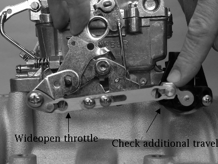
Hold the carburetor linkage in the fully open position. Verify that the throttle position sensor has some remaining stroke / rotation by pressing on the sensor arm as shown above. The sensor should have some additional travel / rotation. If the sensor is fully extended, lengthen the arm slightly to correct.
THE THROTTLE POSITION SENSOR SHOULD NOT REACH THE END OF ITS ROTATION OR STROKE IN EITHER DIRECTION. IT SHOULD BE SLIGHTLY OFF THE STOP AT EACH END OF ITS TRAVEL. FAILURE TO DO THIS COULD RESULT IN POOR OPERATION.
Connecting the TPS

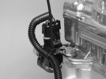
Install throttle position sensor plug into throttle position sensor. The plug has a rubber gasket that is tight fitting. Be sure to push the plug into the socket by squeezing the plug and the sensor together as shown so as not to bend the sensor bracket. This may require two hands.
Your system may have shipped with an extension cable for the throttle position sensor. If necessary, install the extension cable between the controller and the sensor.
Securing the TPS Wiring Harness
Insert the supplied cable tie from the bottom through the slot in the sensor bracket. Close the cable tie around the wire harness. Cut the excess tie length as desired.
Installation of the AccuLink TPS is now complete.