How to Modify A CAN Bus Network
This is a brief outline of typical CAN networks in vehicles and what the rules are about how to modify them.
A Typical CAN Network

This network has three electronic control units (ECU's), and a termination resistor at each end. The wiring between each ECU and the main network is called a stub.
Note that all CAN networks should follow these rules:
Stub distance should be short, <20 cm.
Distance between nodes/ECU must be >10 cm.
Distance between nodes and resistors can be Ø cm.
There are two 120Ω resistors, one at each end of the CAN network.
Wiring is always 120Ω twisted pair, similar to Ethernet, usually with at least 1-2 twists per inch. HGM usually uses 22 AWG unshielded pair made especially for CAN applications.
Variations

In some cases, the termination resistors are inside of an ECU, as shown in this example:
Commonly in factory vehicles, the resistors are inside nodes/ECUs.
The total length of the CAN network can be long, up to 40 meters..
Adding additional nodes along the CAN network is possible following Steps 1-4 (shown below).
Adding an ECU to an Existing CAN Network - Step 1

Cut CAN network cable.
Adding an ECU to an Existing CAN Network - Step 2

Add plugs.
Add plugs to cut terminal ends of wire. As a rule pin 1 is “high” and pin 2 is “low.”
Adding an ECU to an Existing CAN Network - Step 3

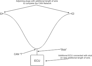
Create extension by adding length of wire with matching plugs, stub, and additional ECU.
Creating additional length of wire with a short stub to a node/ECU will omit interference in BUS network.
If stub is too long, there will be interference. The stub must be short, stub length can be Ø.
Adding an ECU to an Existing CAN Network - Step 4

Connect plugs of extension and of original CAN network to complete the addition of an ECU to an existing CAN network.
