
Install the Power & Engine Harness
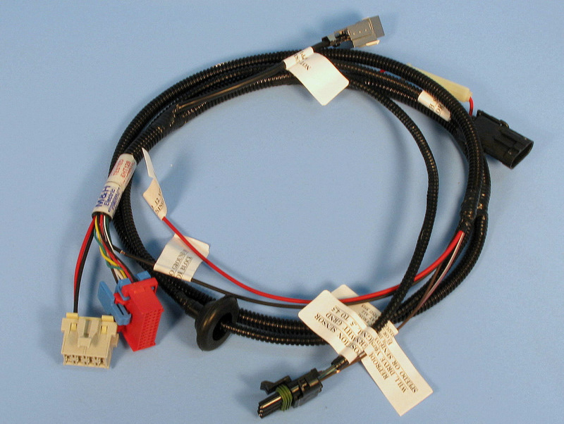
The Power & Engine Harness brings power to the COMPUSHIFT II system and provides several inputs and outputs to the vehicle.
It has two (2) connectors to the Controller (red = Engine, white = Power) and up to five (5) branches, depending on your specifications:
The Power & Engine Harness and its firewall grommet must be safely installed. You can re-position the firewall grommet as needed for your installation.
The harness must be routed so that it never touches the exhaust system, the rotating drive shaft, or other moving parts of the drivetrain.
Connect the Throttle Position Sensor
Depending on your engine type, you may have installed an AccuLink TPS, an EFI TPS adapter, or a Cable TPS system.
Each of these solutions plugs into the same connector on the Power & Engine Harness.
Connect the Power and Meter Leads
- Connect the purple/white wire marked "SPEEDOMETER OUT ADJUSTABLE" to the speedometer.
- Connect the black wire marked "TO GROUND ON BATTERY OR BLOCK" to a good ground, preferably on the negative battery terminal or engine block.
- Connect the brown wire marked "RPM INPUT TO ECM" to either the tachometer output of an electronic ignition system (for example, an HEI), or the tachometer output of an MSD ignition system. This will allow your Display to show your engine RPM.
- Connect the red wire marked "TO 12 VOLTS SWITCHED CLEAN SINGLE CIRCUIT" to a circuit (min. 6 amps of current) that's powered when your ignition switch is turned on.
Do not connect the tachometer input to the coil of an electronic capacitive discharge (CD) ignition. This may damage COMPUSHIFT II and void your warranty.
Connect the Switch-Shift Harness
Switch-Shift lets you manually upshift and downshift the transmission via a pair of pushbuttons or paddle shifters. A separate Switch-Shift Harness connects into the socket on the Power & Engine Harness.
See the section, Install the Switch-Shift Wiring Harness for detailed instructions.
Connect the Overdrive Cancel Switch and Indicator
If using a Ford transmission, you can use this optional feature.
- Connect the blue/red wire to the LED indicator.
- Connect the blue/yellow wire to the switch.
For more information about this feature, see this note in the "Plan" section.
CAN Bus Connector
The CAN Bus allows a direction connection to an Engine Control Unit for engine management and data collection. Certain versions of the HGM software can obtain throttle position, engine speed, manifold pressure, manifold temperature and other information directly from the ECU through the CAN bus. Information on this feature is covered in a software guide specific to that software version.