
Connecting COMPUSHIFT to Link G4+ ECU
Introduction
This guide provides details on setting up a COMPUSHIFT controller to an Link G4+ ECU. These two systems are connected together using CAN bus, and signals like throttle position and engine speed are automatically transferred between the two units. No other connection is required.
Wiring Instructions
The CAN bus wiring kit supplied by HGM has two flying leads that must be crimped to the Link G4+ ECU connector pins and inserted into the appropriate position in the connector.
CAN high is the tan/black wire on the CAN harness.
CAN low is the tan wire on the CAN harness.
Once these are in place, the T connector and terminator portion the harness may be connected to the gray CAN connector on the COMPUSHIFT controller.
Ensure that both units are powered by the same switched ignition power so that they power on at the same time.
Setup Instructions
THESE SETUP INSTRUCTIONS PRESUME KNOWLEDGE OF THE LINK ECU SOFTWARE (PCLINK) AND SETTING UP CUSTOM CAN MESSAGING ON THAT SYSTEM. PLEASE CONSULT WITH HGM AND LINK SUPPORT IF YOU ARE UNSURE ABOUT THE PROCESS. FAILURE TO CONFIGURE THE SYSTEM PROPERLY CAN RESULT IN TRANSMISSION OR ENGINE DAMAGE.
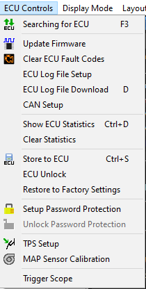
In the PCLink software, connect to your ECU and go to the ECU Controls menu. From there, select the “CAN Setup” option.
This will bring up the CAN setup window. From there, select the “Streams” tab. In the streams tab, choose a stream that is unused. In this example, we are using Stream 3.
Add a single frame to this stream, which will be automatically named “Frame 1”. To this frame, add three parameters as shown:
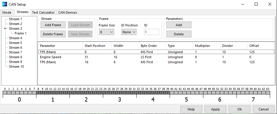
The parameters are as follows:
Parameter | Start Position | Width | Byte Order | Type | Multiplier | Divider | Offset |
|---|---|---|---|---|---|---|---|
TPS (Main) | 8 | 8 | MS First | Unsigned | 1 | 10 | 125 |
Engine Speed | 31 | 16 | LS First | Unsigned | 8 | 1 | 0 |
TPS (Main) | 16 | 8 | MS First | Unsigned | 1 | 10 | 125 |
Note that TPS may be referred to as TP in the PCLink software, depending on the version you are using.
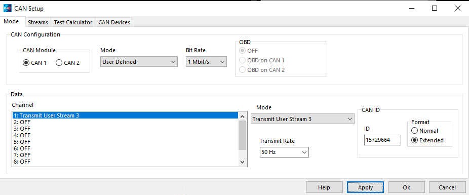
Once you have completed the stream setup, then you must add the stream to a CAN channel. Choose the CAN module the COMPUSHIFT is connected to (usually CAN 1 as shown below), and set the CAN Mode to “User Defined” and the bit rate to “1 Mbit/s”. In the “Data” section of the window, choose an unused data channel, and set the channel mode to “Transmit User Stream”, using the stream number you used in the previous section (our example used 3). Set CAN ID to “15729664” and the CAN ID format to “Extended”. The transmit rate must be set to 50 Hz. The screen capture below shows the example settings:
From the COMPUSHIFT Setup app, be sure that the Vehicle Setup / Engine Type is set to J1939 Gasoline Engine:
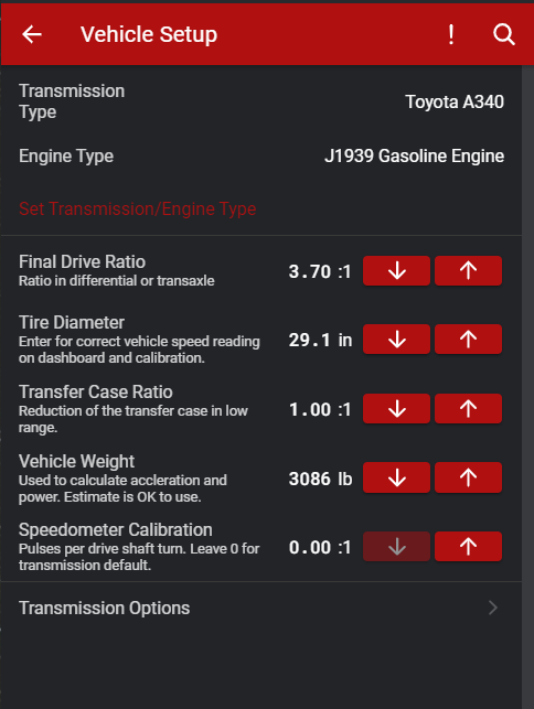
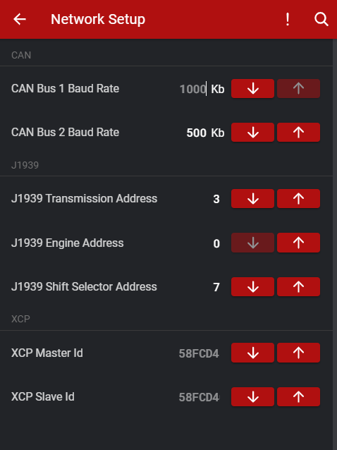
and that the Network Setup / CAN Bus 1 Baud Rate is set to 1000 kb.
This should establish communication between the two systems.
Confirming Setup
Power cycle both controllers and start the engine.
Navigate to the dashboard on the setup app or handheld display of the COMPUSHIFT controller.
Confirm that the engine speed and throttle position are reading correctly on the display.
Confirm that there are no trouble codes on the COMPUSHIFT controller.
If any codes are present, do not drive the vehicle until the problem is resolved. Otherwise, you may damage your transmission.
Do NOT drive the vehicle until you have confirmed CAN communications are working properly and you have no trouble codes.
You can diagnose CAN bus problems by going to Diagnostics / Network Diagnostics on the CS Setup App. The CAN 1 Receive Count should be steadily increasing when the ECU’s are communicating correctly. The error counts should always be 0. If you do have errors, do confirm that the CAN bus baud rate is set correctly in Network Setup.
Related Articles
- Connecting COMPUSHIFT to Link G4+ ECU
- HGM CAN Bus Messaging
- Using and Working with CAN Bus
- How to Modify A CAN Bus Network
- Connectors Used In CAN Networks
- Connecting COMPUSHIFT to Edelbrock ProFlo 4
- Connecting COMPUSHIFT to Haltech Elite or Haltech Platinum
- Connecting COMPUSHIFT to Cummins R2.8 CM2220
- Connecting COMPUSHIFT to Aces EFI
- Connecting COMPUSHIFT to J1939 Engine Management
- Connecting COMPUSHIFT to OBR Control Systems E8G
- Connecting COMPUSHIFT to Holley Sniper 2
- Connecting COMPUSHIFT to Chrysler HEMI Crate Engine
- Connecting COMPUSHIFT to Holley Sniper EFI or Holley TerminatorX
- Connecting COMPUSHIFT to MAST Motorsports ECU's